A mirroring template refers to the environment configuration of a cloud server instance, including the operating system and pre-installed software. Baidu Cloud provides a dedicated public image for each FPGA instance by default, allowing users to choose the most suitable image type based on their needs.
Overview
Based on Baidu Cloud's self-developed FPGA acceleration card, it offers a complete standard development environment for FPGA. Users can utilize the image toolkit provided by Baidu Cloud to develop and debug custom business functions on the FPGA or migrate existing modules to the FPGA accelerator card.
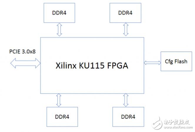
The FPGA accelerator card is built using Xilinx 20nm KU115 FPGA technology. It features four DDR4 channels, each with 72 bits and ECC support, totaling 2GB at 2400MHz. The FPGA is connected to the CPU via PCIe 3.0 x8. Here is the block diagram of the board:
Based on this FPGA board, Baidu Cloud also provides a standard development environment. The system architecture is as follows:
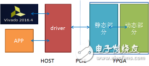
The FPGA standard development environment is highly flexible:
You can develop the dynamic part of the FPGA logic, utilizing most of the KU115 chip resources and the four DDR4 channels, enabling full customization of the FPGA circuit.
Baidu Cloud offers driver and application reference designs, allowing you to modify only the software side of the driver and application to call the FPGA for specific tasks.
You can directly use the toolkit provided by Baidu to replace the dynamic logic of the FPGA.
The environment also includes a virtual JTAG tool that allows debugging with the Vivado tool.
The FPGA standard development environment operates in two parts:
FPGA Software Driver Development
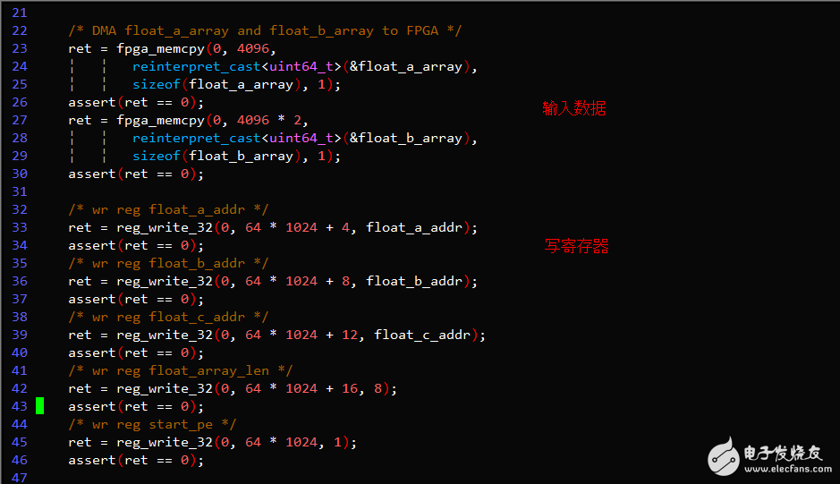
For example, take the sample program that runs the PE for simple floating-point vector addition. The process involves:
1. Compiling the driver and providing a sample program for compilation.
2. Running the sample program.
FPGA Logic Development
Develop and debug user logic using the toolkit:
1. Compile your dynamic logic using Baidu_HW_design_toolkit.
2. Replace your dynamic logic using bin_pr_tools.
3. Debug your dynamic logic using Vivado.
FPGA Software Driver Development
Compiling the Driver
Modify the KERNELDIR variable in the driver/Makefile to point to the current kernel build directory, typically /lib/modules/$(uname -r)/build or /usr/src/kernels/$(uname -r).
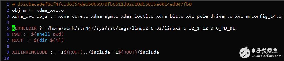
After running 'make', if the compilation is successful, the xdma_xvc.ko driver file will be generated in the current directory, as shown below:
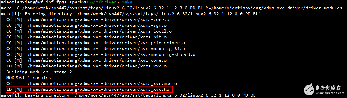
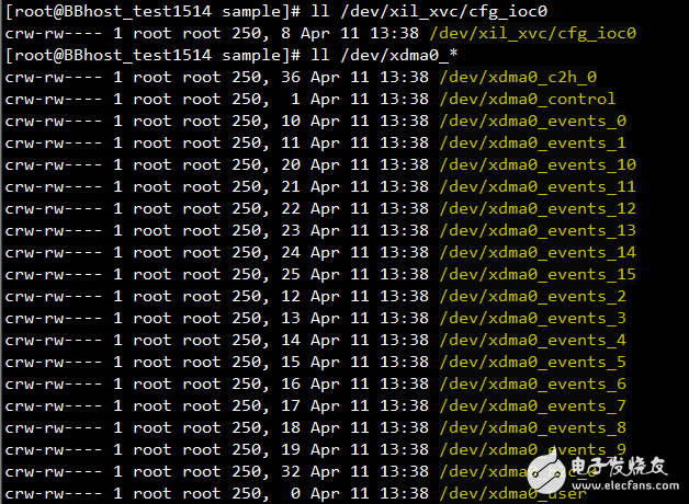
Then, run 'insmod xdma_xvc.ko' to load the driver. This will create the device file /dev/xil_xvc/cfg_ioc0 in the /dev directory.
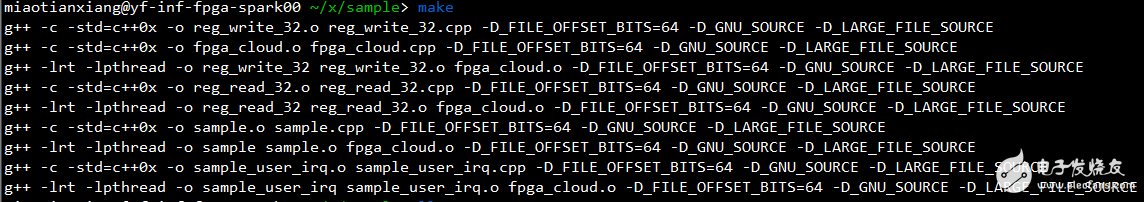
Compiling the Sample Program
Navigate to the sample directory and run 'make'. If the compilation is successful, executable files such as 'sample' and 'sample_user_irq' will be generated in the current directory, as shown in the following figure:
Running the Sample Program
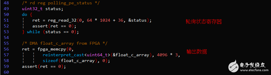
Run './sample' to see the result. The PE correctly performs the floating-point vector addition function. The sample uses the polling register method to check if the command has completed.
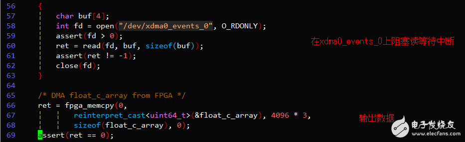
Run './sample_user_irq' to see the result. The PE again correctly performs the floating-point vector addition function, but this time using the interrupt mode to check for completion.
Key Code Example
YIWU JUHE TRADING COMPANY , https://www.nx-vapes.com