Introduction:
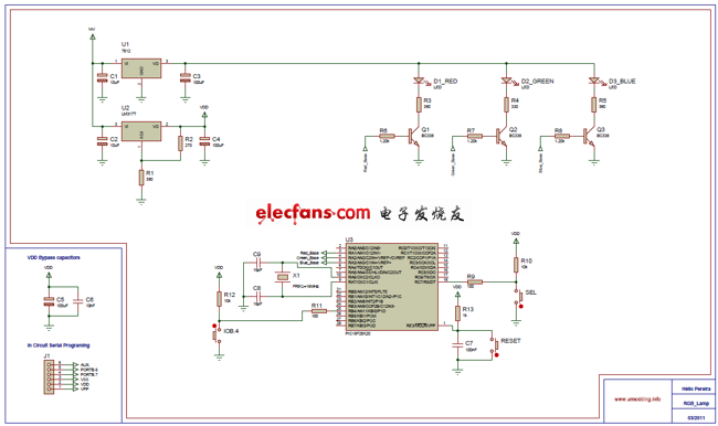
In this project, we utilized a Superfluid RGB LED with a common anode and a PIC18F25K20 microcontroller to create a variety of color combinations. The system features two operational modes: an automatic color sequence stored in the microcontroller's memory and a manual mode where users can select from one of seven possible colors.
Schematic:
Firmware:
PWM (Pulse Width Modulation) controls the RGB LED. Given that the PIC18F25K20 offers only two hardware PWM outputs, I implemented three software-based PWM outputs. I used TIMER0 and set up a manual mode PWM flat change interrupt.
Debounce:
To address the bouncing issue associated with button presses, which arises from the mechanical nature of switches, I employed a software debounce technique. While hardware solutions like RC delay circuits or Schmitt triggers could also work, they would increase costs. Thus, a software approach was chosen for this project. Here’s an example of how I implemented the debounce:
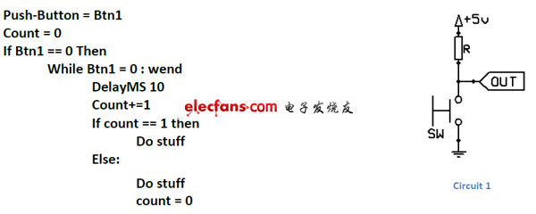
This method proved effective for my application.
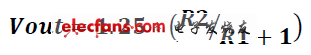
Power Supply:
I used a 7812 voltage regulator to ensure a stable supply for the RGB LED and microcontroller. For the LM317 regulator, I calculated the output voltage using the following formula:
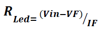
RGB LED:
Since the RGB LED has different forward voltages (VF) for each color, I adjusted the resistances accordingly. The calculations were based on the following equations:
Overall, this project successfully combined the functionalities of RGB LEDs and microcontrollers while addressing challenges like debouncing and power regulation. The end result was a compact, efficient, and visually appealing device capable of producing a wide array of vibrant colors.
The installation process involves sliding the heat shrink tube over the item to be covered and then applying heat, usually with a heat gun, to shrink the tube and create a secure fit. This process provides insulation and protection against abrasion, chemicals, and other potential damage.
heat shrink tube is commonly used in electronics, automotive, aerospace, and other industries where wire and cable management is important. It is a cost-effective solution for protecting and organizing electrical components.
Single Wall Heat Shrink Tube,Heat Shrink Tubing,Heat Shrinkable Protective Tube
Dongguan Liansi Electronics Co.,Ltd , https://www.liansisleeve.com