Introduction
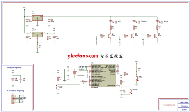
This project uses a Superfluid RGB LED with a common anode and a PIC18F25K20 microcontroller to generate various color combinations. It features two operational modes: an automatic color sequence stored in the microcontroller's memory and a manual mode where users can select from seven distinct colors.
Schematic
Firmware
PWM (Pulse Width Modulation) controls the RGB LED. The PIC18F25K20 has only two hardware PWM outputs, so I implemented three PWM outputs using software. I utilized TIMER0 and configured the manual mode PWM flat change interrupt.
Debounce
In this project, buttons were used to switch between the two modes and change the color. However, switches inherently suffer from mechanical bounce issues, which could cause unintended actions. To address this, I opted for a software debounce solution instead of increasing costs through hardware solutions like RC delay circuits or Schmitt triggers. Here’s an example of the debounce code:

This method works well for my application and ensures reliable button presses.
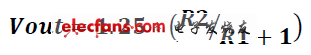
Power Supply
I employed a 7812 voltage regulator to maintain a stable supply for the RGB LED and microcontroller. For the LM317 voltage regulator, I used the following formula to calculate the output voltage:
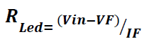
LED RGB
Different resistances were applied to the RGB LED based on their varying forward voltages (VF). These calculations were performed using the following equations:
Non-slip Heat Shrink Tube,Heat Shrink Tube,Silicone Heat Shrinkable Tube
Dongguan Liansi Electronics Co.,Ltd , https://www.liansisleeve.com