The M9000 camera battery is commonly found on the market, typically assembled from a series of nickel-metal hydride (NiMH) cells. These batteries are usually rated at 12V with a capacity of 1.8Ah or 2.1Ah. However, when using the original camera charger, the battery tends to overheat—often reaching temperatures above 50°C. This overheating becomes more frequent with repeated charging, leading to rapid decomposition and evaporation of the electrolyte. Eventually, the battery pack becomes unusable, and even after charging, it often doesn’t hold enough power.
The original charger is designed for maintenance-free lead-acid batteries, operating at a nominal voltage of 12V or 14V with a current of 1.5A. It’s not suitable for NiMH battery packs because the current is too high and the voltage is too low. Last year, I built a custom charging circuit that has worked reliably for over a year. It’s used to charge NiMH batteries for several cameras. The charging parameters are as follows: the ratio of battery capacity to charging current is 10:2, and the voltage ratio is approximately 1:1.5. Charging takes about 5 hours, and the battery charges fully without any overheating.
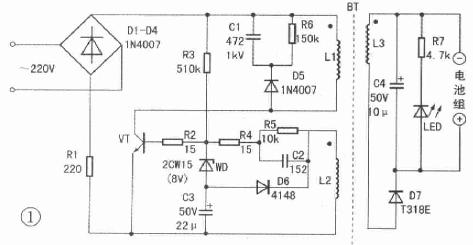
As shown in the diagram, the AC supply is rectified by D1–D4 to produce a 200V DC voltage, which powers an oscillating circuit made up of components like VT, C1, C2, R5, R6, L1, L2, etc. The pulse voltage from the secondary winding L3 of the transformer BT is then rectified and boosted through D7 and C4 to generate a 18–19V half-wave DC output, with a current of around 500–600mA. This is sufficient to charge a 12V NiMH battery pack with a capacity of about 2000mAh.
The transformer BT can be made from an E-type ferrite core taken from an old fluorescent lamp ballast. L1 is wound with 120 turns of 0.18mm wire, L2 with 10 turns of 0.18mm wire, and L3 with 25 turns of 0.26mm wire. The transistor VT can be a C2271, C1507, or 3DA87E with a BVceo rating of at least 350V. Ceramic capacitors are used for C1 and C2, while resistors are 1/4W type. Diodes should be selected according to the schematic. If the output voltage is too low, you can adjust the number of turns on L3. Soldering is straightforward, and there’s little room for error.
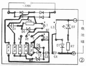
The printed circuit board can be designed and manufactured based on the provided diagrams (note that the transformer is not mounted on the PCB). This homemade charger offers a safe, efficient, and cost-effective solution for charging NiMH batteries in older cameras like the M9000.
DongGuan BoFan Technology Co.,Ltd. , https://www.ufriendcc.com