Playing the sound, the wire is a hurdle. From the end of the 1970s, some audio technicians and enthusiasts in Europe and America found that the wire has a significant effect on the sound, and began to consciously increase the diameter of the audio wire conductor to reduce the transmission resistance. In the mid-1980s, Japan developed high-purity conductors for acoustic wires by developing metal smelting and purification technologies. 4N, 5N, and even 6N high-purity oxygen-free copper were successively developed. In the 1990s, Japan's Furukawa Electric invented the method of smelting single crystal copper to push the purity of wire conductors to the extreme. The wire and wire manufacturers in Europe and the United States have made their own sound-tuning concepts by changing the wire structure and weaving methods, and have achieved remarkable results. Along with the development of wire technology, its price has also climbed from hundreds, thousands, tens of thousands, and hundreds of thousands. At the same time, the controversy about wire rods has never stopped, and some have more than one million. Equipment, but only a few hundred dollars of wire, but also a full set of wire prices exceed the full set of equipment. In the country's major audio forums, the wire posts are often useful in the debate, and no one can convince anyone. Ethan Winer, a well-known foreign enthusiast, is a recording engineer, cellist, circuit designer, and software engineer. He has made achievements in all areas of audio technology, and completely denies audio wires in his writings. The exaggerated effect is that as long as the electrical parameters of the wire are the same, the sound produced by the expensive wire and the low-priced wire is no different, and this view is proved by the homodyne detection.
From the first time I heard the difference of wire rods, I started to play the line, and became the domestic agent of imported brand wire. For more than ten years, I have never stopped thinking and trying on wire, and taught myself the theory of transmission line, electrodynamics, solid physics, Electromagnetism and other disciplines related to audio wire, to explore the theoretical basis of wire tuning. This issue of the article, share your long-term practice and thinking experience with everyone. It should be noted that since the author is not a professional in wire research, this discussion is different from scientific papers. Some opinions may be biased. Some terminology is not accurate enough and is only for your reference, and welcomes criticism.
There are several digital audio cable lines, signal lines, horn lines, power lines, etc., this article specifically say why the power line it? The reason is that for several other audio wires, the transmission line theory has revealed the mystery of these wire tuning through the following equivalent circuit model. And by measuring the corresponding electrical parameters of the wire, and the actual sense of hearing, used to guide the design of the wire.
Figure 1. Equivalent circuit model of a transmission line
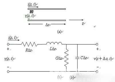
R = series resistance per unit length in two conductors, in Ω/m
L = series inductance per unit length in two conductors, in H/m
G = parallel conductance per unit length in two conductors, unit S/m
R = parallel capacitance per unit length in two conductors, unit F / m
For the power line , although the above circuit model is still established, its electrical parameters cannot be related to the sense of hearing, and the following two fatal problems cannot be answered:
Question one:
The power line goes from the residential transformer to the building distribution box to the home of the enthusiasts. The length of the power line is at least tens of hundreds of meters. The front is used for ordinary low-voltage wires and cables of several yuan or ten yuan and one meter. Why only replace the last one? Two meters can make a huge change to the sound?
Question 2:
The signal line and the speaker line transmit the music signal, and the distribution parameter of the wire causes a slight distortion of the signal and the current, resulting in different senses of hearing. However, the power line transmits only 50/60HZ AC, and the frequency is extremely low. As long as the overcurrent capability is sufficient, how can the effect of the sound be affected by the slight inductive reactance and capacitive reactance? Who can detect the changes in the waveform after the 50Hz AC is passed through the wire?
These two problems are the killers of the " power line useless". So far, the author has not seen a scientific and reasonable explanation of these two issues. Even the top fever wire manufacturers, avoiding these two problems, only promote what materials and structures are used in their power cords , and how they will improve the sound. This is like a Chinese medicine practitioner. I only know that a certain soup can treat a certain disease. What is the active ingredient of this soup? What is the mechanism of its action? There is no comment. Of course, they are not excluded from knowing the mechanism by which the power cord changes sound, but it is never leaked as a technical secret. Even with another set of rhetoric, talk about the "story" of the power cord .

I remember that many years ago, the author re-adjusted the position of the audio equipment, and the power cord was not long enough, so the two power cords were temporarily replaced with connectors. The two power lines are equivalent to two resistors. According to the common knowledge of the electrician, the placement of the resistors in the series circuit does not have any influence on the voltage and current of the circuit. Therefore, the order of the circuits is not noticed at the time, but they are randomly inserted together. After listening to it for a few days, I thought about changing the position of the two power cords . The result was very different: the power cord next to the equipment had a greater impact on the sound! At that time, the author's preliminary speculation on this phenomenon is that the audio equipment is a non-linear load, and it will generate a "harmonic impact" on the power supply line during work (use this name, perhaps not enough), through the pair of equipment The structure and material design of the one or two-meter power cord can be combined with reasonable "electrical parameters" to buffer the impact of combing harmonics to a certain extent, so that the power supply is more orderly and sufficient.
The above speculations better answer the first question above, but still have to be verified by experiments and test data. And for the second question raised earlier, further research is needed. To this end, the author has specially purchased the relevant instruments to test what happens to the power supply when the audio equipment is working.
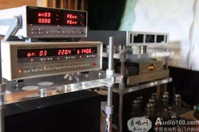
When there is no access to the latter stage, the power supply quality of the author's home is very good, the voltage is 220V, and the harmonic voltage component is 0.8%, which fully meets the national power quality standard. However, after the latter stage was turned on, although the harmonic voltage slightly increased to 1.0%, the harmonic current ratio increased sharply to 140.6%.
That is to say, when the audio equipment is working, not only the 50Hz power frequency current flows in the power line , but also a large number of 100Hz~2500Hz (the instrument can only measure 2~50 harmonics, which may actually be higher). Harmonic current, the total amount even exceeds the current intensity of the fundamental frequency of 50Hz!
The 50Hz power frequency current belongs to the low frequency category, the electromagnetic field changes frequency is low, and the electromagnetic radiation level is also low, but the harmonics above 2000Hz will cause electromagnetic radiation that cannot be ignored. In addition, the high-frequency electromagnetic waves generated by the internal circuit when the equipment is working are transmitted under the constraint of the power line conductor. The propagation speed of electromagnetic waves in a good conductor is very slow. For example, a 1 MHz electromagnetic wave propagates inside a copper core conductor at a speed of only about 400 meters per second, and is rapidly attenuated. When a reflective interface or propagation medium is encountered, a strong reflection is produced. (This also explains why the power supply head and socket, the inconspicuous gadgets, why the impact on the sound is so large). Part of the electromagnetic wave is absorbed by the conductor, insulator and shielding layer, and a part of it is reflected back into the wire conductor and the inside of the equipment, which will double the distortion and phase distortion of the input current waveform (as shown in the figure below).
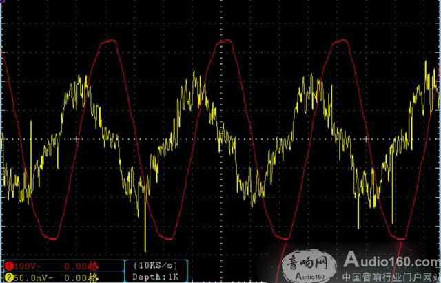
Note: Red is the voltage waveform, yellow is the current waveform. The power amplifier is essentially a valve. It can not losslessly amplify the music signal, but uses the music signal to control the output current (voltage). There will be rectification and filtering circuits inside the equipment, but the sharply changing input current will often exceed the adjustment ability of the filter circuit, and eventually the output signal or power current will fluctuate and dye, thus changing the sound.
The author also connected a brand of parallel power supply processor to the same socket of the latter stage, the total amount of harmonic current was immediately reduced, which proves that this power processor is effective.
Therefore, the author's answer to the second question raised above is: If the power line is connected to a purely resistive load, the change of the power supply waveform of the different power lines is negligible or even undetectable. However, for non-linear loads such as audio equipment, a large amount of high-frequency harmonic currents and electromagnetic waves are generated during operation, and as the music signal changes rapidly, different electrical parameters of the power line will affect harmonic currents and electromagnetic waves. The process of change affects the audio or power signal output of the equipment.
We adopt the advanced technology imported from Europe, patented technology, specialized software to optimize the design for33kV cast resin Dry Type Transformer. The core is made of cold-rolled grain-oriented silicon steel sheet which cut in step-lap by GEORG Germany TBA core cutting lines and laminated by the method of fifth-order step-by-step stacking technology, enabling the no-load performance of the core to improve greatly. The epoxy resin from American HUNTSMAN is adopted for the windings which casted in the vacuum resin casting machine imported from HEDRICH, Germany. The winding material ensures good permeability, no bubbles occur, which leads to minimum partial discharge. The HV and LV winding mate with each other tightly, which ensures solid strength of structure and capability to withstand short circuit and vibration. Under normal service condition, the service life of dry type transformer is 30 years. No crack will form on the surface of transformer winding due to temperature variation as long as the transformer runs under normal service condition.
Earthing Transformer,33Kv Dry Type Transformer,33Kv Transformer,33Kv Cast-Resin Transformer
Hangzhou Qiantang River Electric Group Co., Ltd.(QRE) , https://www.qretransformer.com