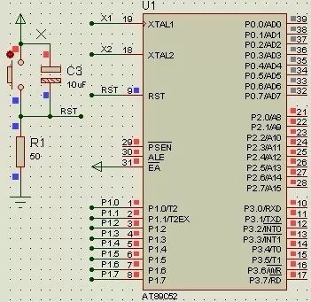
As observed, when the resistor R1 is set to 10kΩ in the reset circuit, the RST pin remains high. However, when R1 is 50Ω, the RST pin goes low. This clearly indicates that using a 10kΩ resistor is incorrect because it causes the microcontroller to remain in a reset state, making it impossible for the device to function properly. The reason for this issue lies in the internal structure of the RST pin, which contains a transistor. Even when off, there is a small leakage current. When the resistor value is too high, this tiny current can still pull the pin to a high level, preventing the microcontroller from starting up correctly.
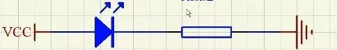
Second, calculating the LED series resistance
Typically, red LEDs have a forward voltage range of 1.6V to 2.4V and operate at currents between 2mA and 20mA. The brightness increases with current, but after about 5mA, the change becomes less noticeable. It’s important to choose the right current-limiting resistor to ensure proper operation without damaging the LED.
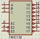
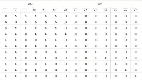
Third, insufficient I/O ports
When the number of available I/O pins on the microcontroller is not enough, an external chip like the 74HC138 decoder can be used to expand the port count. This allows more devices or signals to be controlled through the microcontroller.
Fourth, filter capacitors
Filter capacitors are divided into high-frequency and low-frequency types. High-frequency capacitors, typically 0.1μF (104), are used to suppress noise and protect the IC from interference such as static electricity. These are usually placed between power and ground. Low-frequency capacitors, often electrolytic (e.g., 100μF), help smooth out power supply ripples and stabilize the voltage. They are commonly placed near high-power components like motors or displays and should have a voltage rating at least twice the system's maximum voltage.
The role of the fifth transistor
1. Switch Function:
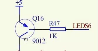
When the base is high, the LED turns off. When the base is low, the LED turns on. To calculate the current-limiting resistor, if the collector current is I, the base current is approximately I/100 (assuming a gain of 100). The resistor value can be calculated as R = (5 - 0.7) / (I/100).
2. Amplification: The collector current is 100 times the base current.
3. Level Conversion:
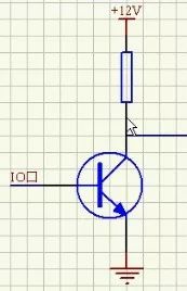
When the base is high, the transistor turns on, pulling the output low. When the base is low, the transistor turns off, allowing the output to go high.
Sixth, digital tube issues
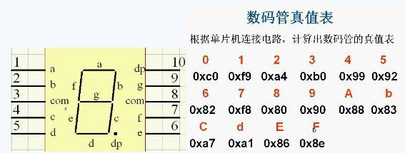
A seven-segment display lights up segments a, b, c, d, e, f, g, and dp (decimal point) to form numbers. The truth table and segment configuration are shown above.
Seventh, current and voltage drive problems
Microcontrollers have limited output capability. If multiple loads are connected, a driver chip like the 74HC245 may be necessary to provide sufficient current and prevent damage to the microcontroller.
Eighth, pull-up resistor
Pull-up resistors are used to keep a signal at a known high level when no active device is driving it. Key considerations include: 1. Power efficiency: A higher resistance reduces current consumption. 2. Drive capability: A lower resistance ensures stronger signal strength. 3. For high-speed circuits, very large pull-up resistors may cause signal distortion. Common values range from 1kΩ to 10kΩ. Pull-down resistors serve similar purposes, ensuring stable logic levels and reducing noise on floating pins.
Ninth, crystal and reset circuit
Crystal Oscillator Circuit
1. Crystal selection: Choose based on system requirements—common frequencies include 6MHz, 12MHz, 11.0592MHz, and 20MHz. 2. Load capacitance: Connect two 10–30pF capacitors to ground, typically 20pF. 3. Measuring the crystal: Use a multimeter to measure the voltage between one crystal pin and ground.
Reset Circuit
The reset circuit initializes the microcontroller by resetting its internal registers. For the 51 MCU, the reset time is about two machine cycles, depending on the specific chip. Calculating the correct resistor and capacitor values is essential, and this is often done via online resources or datasheets.
Tenth, button debounce
Buttons, being mechanical, produce contact bounce when pressed or released, as shown below:
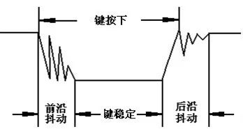
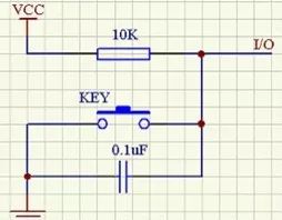
There are two common methods to eliminate this: hardware and software debouncing. Hardware debouncing uses a capacitor to short out high-frequency noise. Software debouncing involves detecting a key press, waiting for 5–10ms, and then rechecking the signal to confirm a valid press.
Intel Mini Pc,Mini Computer,Intel Nuc,Mini Cpu
Guangdong Elieken Electronic Technology Co.,Ltd. , https://www.elieken.com