The power grid supplies AC power to users, and various radios require DC power. Rectification is the process of turning AC power into DC power. By using a device having unidirectional conduction characteristics, a current alternating in direction and size can be converted into direct current. The various rectifier circuits composed of crystal diodes are described below.
One, half wave rectifier circuit
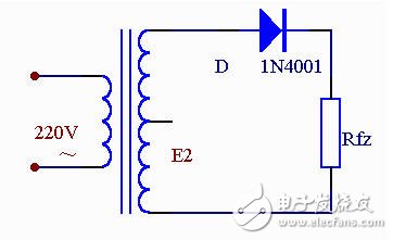
The picture above is the simplest rectifier circuit. It consists of a power transformer B, a rectifier diode D and a load resistor Rfz. The transformer converts the mains voltage (mostly 220 volts) into the required alternating voltage e2, which in turn converts the alternating current into pulsating direct current.
Let's see how the diode is rectified from the waveform diagram.

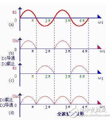
The transformer cut-off voltage e2 is a sine wave voltage whose direction and magnitude change with time. Its waveform is shown in Figure 5-2(a). In the 0 to K time, e2 is positive half cycle, that is, the upper end of the transformer is negative at the lower end. At this time, the diode is subjected to the forward voltage surface conduction, and e2 is applied to the load resistor Rfz through it. In the period of π~2π, e2 is a negative half cycle, and the lower end of the transformer is positive and the upper end is negative. At this time, D is subjected to reverse voltage, no conduction, and no voltage on Rfz. In the π~2π time, the process of 0~π time is repeated, and in the time of 3π~4π, the process of π~2π time is repeated... This way, the negative half cycle of the alternating current is "cut", only positive Half-cycle through Rfz, a single right-direction (upper-down-down) voltage is obtained on Rfz, as shown in Figure 5-2(b), for rectification purposes, however, the load voltage Usc. And the magnitude of the load current also varies with time, so it is often referred to as pulsating DC.
This rectification method of removing the half cycle and the lower half of the figure is called half-wave rectification. It is not difficult to see that the half-wave symmetry is exchanged for the rectification effect at the expense of "sacrifice" half of the AC, and the current utilization rate is very low (calculation shows that the average value of the half-wave voltage obtained by rectification in the whole cycle, that is, the load The DC voltage Usc = 0.45e2) is therefore commonly used in high voltage, low current applications, and is rarely used in general radios.
Second, full wave rectifier circuit
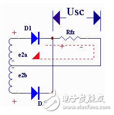
If the structure of the rectifier circuit is adjusted, a full-wave rectifier circuit that can fully utilize the power can be obtained. The figure below is an electrical schematic of a full-wave rectifier circuit.

The full-wave rectification circuit can be considered as a combination of two half-wave rectification circuits. In the middle of the secondary winding of the transformer, a tap is drawn to divide the secondary coil into two symmetrical windings, thereby extracting two equal voltages e2a and e2b of opposite polarity to form e2a, D1, Rfz and e2b, D2, Rfz, Two energized circuits.
The working principle of the full-wave rectifier circuit can be illustrated by the waveform diagram shown in Figure 5-4. Between 0 and π, e2a is a forward voltage for D1, D1 is turned on, and a positive and negative voltage is obtained on Rfz; e2b is a reverse voltage for D2, and D2 is not conductive (see the figure below at π-2π). During the time, e2b is forward voltage for D2, D2 is turned on, and the voltage obtained on Rfz is still positive and negative; e2a is reverse voltage for D1, and D1 is not conductive (see the following figure for repeated, due to The rectifying elements D1 and D2 are alternately conducting. As a result, during the positive and negative two half cycles of the load resistance Rfz, the current flows in the same direction, as shown in the figure, so it is called full-wave rectification, and full-wave rectification is not only The positive half cycle is utilized, and the negative half cycle is also skillfully utilized, thereby greatly improving the rectification efficiency (Usc = 0.9e2, which is twice as large as that of the half wave rectification).
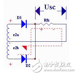
The full-wave splicing circuit shown in Figure 3 requires the transformer to have a secondary center tap that is symmetrical at both ends, which causes a lot of trouble in production. In addition, in this circuit, the maximum reverse voltage that each rectifier diode is subjected to is twice the maximum value of the secondary voltage of the transformer, so a diode capable of withstanding higher voltages is required.
Charcoal BBQ Grill,Charcoal Smoker BBQ Grills,Charcoal Barbecue Grill,Charcoal Grill
Shaoxing Haoda Electrical Appliance Co.,Ltd , https://www.zjhaoda.com