Abstract A design method of intelligent tracking model vehicle hardware system based on infrared laser diode is introduced. The system uses MC9S12XS128 as the control core, adopts infrared laser diode and infrared receiving sensor to collect path information, and uses the MC33886 chip with integrated H-bridge circuit to drive the motor, and uses LM331 chip to design the speed measuring circuit. The system can analyze and process the collected path information and the feedback speed data, and can control the steering of the steering gear and adjust the motor speed in time to realize the automatic tracking function of the trolley.
Key words path identification; smart car; infrared laser diode; MC33886; automatic tracking
The national "Freescale" Cup smart car competition is based on the standard model car platform, using Freescale Semiconductor's 8-bit, 16-bit microcontroller as the core control module, by adding road sensors, motor drive circuits and writing The corresponding software, a model car that can identify the road by itself, travels according to the prescribed route, and the shortest completion time is the winner. The competition covers content from control, pattern recognition, sensing technology, electronics, electrical, computer and mechanical. Based on this competition, this paper designed a smart car control system. This system proposes an implementation scheme based on the principle of laser strong reflection for the path detection of smart cars, and achieves high-precision path detection. The system uses the MC9S 12XS128 controller to analyze and process the information of the black guide line of the road collected by the infrared receiving sensor and the speed information fed back by the speed measuring module, and then according to the deviation between the black guide line in front of the road and the center line of the vehicle body. The control signals are respectively sent to the steering gear and the motor drive module, thereby controlling the vehicle to achieve fast and stable autonomous tracking.
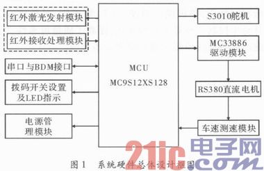
1 system hardware overall design scheme The system hardware design mainly consists of MC9S12XS128 control core, power management module, laser transmitting and receiving module, steering gear control module, DC motor drive module, vehicle speed detection module, serial port and debugging interface module, digital switch and LED The indicator module is composed of the same system, and the whole system constitutes a speed closed-loop control system, and its structure is shown in FIG. In the figure, the dial switch and LED indicator module are mainly used to select the running mode of the vehicle, and several running algorithms can be realized in the program, and the quick switching can be realized by the dial switch to adapt to different operating environments.
This article refers to the address: http://
2 The core control board of the core control board design system is the smallest hardware system of the MC9S12XS128. It is composed of MC9S12XS128 chip, clock crystal oscillator circuit, reset circuit, BDM interface circuit, RS232 serial port circuit, filter capacitor, inductor and connector. The S12XS series MCU is a single-chip microcomputer that removes the XGate coprocessor based on the S12XE series. It uses the S12X V2 CPU core and can run on a 40 MHz bus frequency with an ECC module, two SPI modules, and two CAN bus modules. At the same time, two SCI serial communication modules support LIN bus, four external events trigger interrupt input port, eight 16-bit counters, eight PWMs and 16 8-bit, 10-bit, 12-bit A/D, and the conversion time is 3μs. The BDM interface can be used to download programs to the target board, as well as basic debugging functions such as setting breakpoints, reading and writing memory, reading and writing registers, stepping through programs, running programs, and stopping program running. In addition, the collected path data and other test data can be uploaded to the PC through the serial port.
3 module circuit design
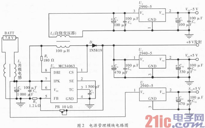
3.1 Power Management Module Power modules provide positive and negative dual power supplies for operational amplifiers in addition to power supplies for microcontrollers, sensors, servos, and motor drives. Therefore, a variety of voltage values ​​are required to meet the requirements of each module. In addition, the Ni-cd battery used in the design has a no-load voltage of about 8 V when the battery is fully charged, and the voltage gradually decreases as the battery is consumed. In addition, if the current is too large when the motor starts and reverses braking, the battery voltage may be pulled lower. In order to avoid the normal operation of the MCU and the sensor and its signal amplifying circuit due to the instability of the power supply voltage, the power supply design uses the DC-DC converter chip MC34063 and the low differential voltage regulators LM2940 and LM2990. The MC34063 outputs a stable +8 V voltage to the laser emitting diode, and the LM2940 converts +8 V to +5 V to provide positive power to the operational amplifier circuit and the speed measuring circuit. The op amp's negative supply is sensed by a self-winding transformer L2 to output a -8 V voltage, which is then regulated by the LM2990 to a -5 V supply. The +5 V voltage required by the MC9S12XS128 microcontroller and the infrared receiver circuit is directly regulated by the battery voltage directly connected to the LM2940. A common mode inductor L1 is also connected between the Ni-cd battery and the power input as isolation, so that the motor drive circuit can be connected to both ends of the battery, thereby ensuring the power of the motor and effectively suppressing the high frequency interference string generated by the motor. In the power module, it also ensures the stable operation of the system at various speeds. The circuit principle of its power management module is shown in Figure 2.
3.2 The infrared laser transmitting and receiving module includes two parts: an infrared emitting sensor and an infrared receiving sensor. In order to make the car have the advantages of long-term and high precision, the system uses infrared laser diode HLD780060H7J as the infrared emission sensor. The transmitter is a semiconductor laser diode emitting a wavelength of 780 nm, operating voltage of DC=2 V, operating current <125 mA, and transmitting power up to 60 mW. The reflection effect can meet the requirements. The focusable lens not only doubles its emission capability, but also realizes the function of adjustable precision. It is necessary to adjust the focusing accuracy of the lens as long as it is slightly adjusted. The receiver can use a high sensitivity silicon phototransistor. The detection principle of the path of the smart car is that the infrared light emitted by the infrared laser emitting tube is reflected back after encountering an object with strong reflectivity, and is received by the photodiode, so that the photo-generated current of the photodiode is increased, and then this is A change current is converted into a voltage signal, and A/D conversion and comparison judgment are performed by the processor, thereby realizing recognition of two objects having different light reflectivities.
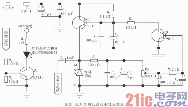
The schematic diagram of the specific infrared transmitting and receiving circuit is shown in Figure 3. The left half of the figure is the infrared laser transmitting circuit. As can be seen from the transmission circuit diagram, only one transistor Q1 (N5551) can directly drive the infrared laser diode HLD780060H7J, and its control signal is a 40 kHz modulation signal, which is generated by the controller. The right part of the figure is the infrared receiving circuit, and the infrared receiving photodiode is a PN junction, which needs to provide a reverse bias voltage, so the reverse connection is in the circuit. The circuit formed by the transistors Q1 and Q2 does not function as a signal amplification, but causes the operating point of the photosensitive sensor to change due to changes in ambient light, thereby ensuring the sensitivity of the sensor receiving. To a certain extent, it plays an adaptive role in the ambient light. During the debugging process, the signal output of the sensor can be maximized by adjusting the variable resistor PR1. The amplifier circuit can be designed with a low-noise operational amplifier TL064. The chip integrates four op amps for easy signal filtering and multi-stage amplification. The amplified signal is passed through the RC integration circuit to generate the voltage to be acquired by the A/D. Since the track of the Freescale Smart Car Race consists of a white foam material and a black guide wire in the center, the black guide wire can be identified by comparing the A/D sample values ​​of the two.
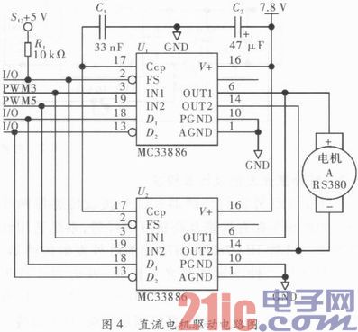
3.3 RS380 DC motor drive module DC motor drive uses Freescale's 5 A integrated H-bridge chip MC33886. The chip contains a control logic, charge pump, gate drive circuit and low on-resistance MOSFET output circuit for controlling inductive DC loads. The chip provides continuous 5 A current and integrates overcurrent protection, overtemperature protection, and undervoltage protection circuitry. By controlling the four input pins (IN1, IN2, D1, D2) of the MC33886, the motor can be rotated forward, energy brake and reverse brake. In this application, the role of the MC33886 is to modulate the constant DC voltage into a sequence of PWM pulse voltages with the same frequency and variable pulse width, thus changing the average voltage of the output to control the motor speed. In order to improve the control precision of the DC motor, the PWM2 and PWM3 two-channel 8-bit registers of the MC9S12XS128 microcontroller can be cascaded into 16-bit registers, and output from the PWM3 channel to the IN1 of the MC33886. Similarly, the PWM4 and PWM5 two-channel 8-bit registers can also be cascaded into a 16-bit register, which is connected to the IN2 of the MC33886 from the PWM5 channel output. By controlling the IN1 and IN2 of the MC33886 through PWM, the control of the four-quadrant operation of the motor is realized. The DC motor RS380 is directly connected to the output terminals OUT1 and OUT2 of the MC33886. The drive design uses two MC33886s in parallel to reduce the influence of on-resistance on the characteristics of the DC motor and enhance the ability to drive the motor. On the other hand, it can reduce the internal overcurrent protection circuit of the MC33886 to start and brake the motor. The influence and share of the heat generation further improve the performance of the motor drive.
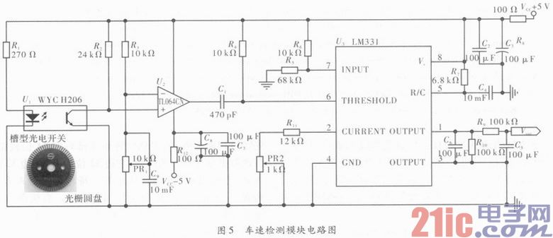
3.4 Vehicle speed measuring module In order to realize the intelligent acceleration and deceleration of the track car, so that the vehicle can track the guide line at high speed and smoothly, it must detect the speed and make the speed of the vehicle form a closed-loop control relationship. The system's speed detection is achieved by a combination of a low-cost slot photoelectric switch H206 and a grating disk. It is a light-transmitting detection method. The principle is shown in Figure 5. When the grating disk rotates along the axis to be measured, the light of the left LED in U1 can only be irradiated to the right side of the light through the hole in the grating disk. On the tube; when the photocell is illuminated, its resistance is small, so a low-level signal is transmitted to the mountain; when the light source is blocked by the disc, the photoelectric tube has a large resistance, and the output terminal forms a high-level signal output. A standard rectangular pulse is then generated by a voltage comparator consisting of a South U2. However, the number of small holes on the disc is the same, that is, the number of pulses per revolution is the same. If the speed changes, the number of pulses output will also change, and the change is linear. Then according to v=(N/M)/T (v is the rotation speed; N is the number of pulses generated in unit time T; M is the number of holes on the grating disc; T is the unit time), the measured axis can be calculated. Speed. However, in order to improve the efficiency of the speed measurement, the system adopts another conversion method, which is to convert the pulse signal into a level signal and then sample the corresponding speed value by the single chip A/D sampling. The LM331 chip in the network constitutes an F/V conversion circuit. The detection pulse is input from the 6-pin of the LM331 chip, and a voltage signal is output from the pin 1, and then sent to the A/D sampling of the single chip microcomputer, and different sampling values ​​correspond to different rotation speeds.
3.5 The assembly system of the steering gear module and the trolley adopts the Futaba S3010 steering gear. There are only three lead wires, which are ground wire, power wire and PWM control wire. The essence of the steering gear is a position following system, which consists of a steering wheel, a reduction gear set, a position feedback potentiometer, a DC motor and a control circuit. Through the internal position feedback, the steering wheel output angle can be proportional to its given control signal. That is, if the load torque is less than its maximum output torque, its output angle will be proportional to the given pulse width. In order to improve the response speed of the servo, connect its working voltage directly to the battery voltage of 7.2 V, and cascade the two 8-bit outputs of PWM0 and PWM1 into a 16-bit PWM, and then output the PWM1 channel to the rudder. machine. In practice, the response speed of the steering gear can be further improved by taking the method of lengthening the steering arm to increase the swing.
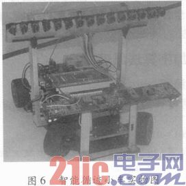
Figure 6 is a physical diagram of the assembly of the intelligent tracking trolley of the present design. The effect of the sensor on the track information capture will directly affect the control strategy of the smart car and its speed. In order to obtain the largest possible preview, as shown in Figure 6, the design is to fix 15 equally spaced laser sensors at a position of about 25 cm from the ground and shoot at a front angle of 58° to make the car look forward. 40 cm. At the same time, the steering gear is raised through the pad, which lengthens the length of the front wheel control arm, thereby improving the response speed of the front wheel steering. A heat sink is added to the surface of the motor and its drive MC33886 to improve the performance of the motor. Through scientific hardware design and reasonable algorithms, the system can obtain the track information in advance and make immediate and correct decisions, so that the vehicle can decelerate in advance in the curve, and accelerate the road ahead to save more distance. path.
4 Conclusion paper for the analysis and design of intelligent car tracking hardware system based on infrared laser diode. The hardware circuit design of the controller module, power management module, path identification module, motor drive module, vehicle speed measuring module and steering gear module of the smart car is introduced, and the actual circuit diagram of some modules is given. The physical map of the intelligent tracking car was finally displayed. Practice has proved that the car can achieve tracking function quickly and smoothly.
Guangzhou Ehang Electronic Co., Ltd. , https://www.ehangmobile.com