Abstract: Based on the GSM/GPS module, the article designs and implements a new type of network car anti-theft system. The system uses GPS positioning technology to obtain the position of the vehicle, uses the sensor to determine whether the vehicle is abnormal, and uses the GSM network to notify the vehicle owner of the vehicle status information through SMS (short message service). At the same time, it can also receive control commands from the owner or monitoring center, so as to realize automatic alarm, automatic control, automatic information inquiry and other functions for the vehicle, and realize two-way communication with the user.
Keywords: global positioning system; global mobile communication system; single chip microcomputer; car anti-theft system
0 Introduction With the advent of the new era, cars have also developed rapidly as important means of transportation. At the same time, the number of car thefts has increased. However, most of the car anti-theft systems on the market currently have certain limitations. Therefore, a network-based anti-theft system with high reliability and security has gradually entered the field of vision. Network-based anti-theft mainly breaks through the limitation of distance, solves the passive anti-theft method of traditional physical anti-theft device, integrates advanced GPS positioning system and GSM communication system module, and uses SMS (short message service) to send and receive text messages to the owner. Two-way communication between users. The interactive, active alarm mode not only informs the owner of the car before it is illegally moved, but also remotely controls the vehicle via the network. This project is a kind of intelligent anti-theft system for the public that is developed by GPS and GSM network and is more reliable and safe.
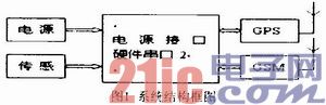
1 System overall design system is mainly composed of GSM module, GPS receiver module, single-chip control circuit, sensor alarm circuit and power supply circuit. The sensor alarm module monitors the abnormal condition of the vehicle; the GPS module is responsible for receiving the positioning data; the single chip control circuit collects, receives and analyzes the GPS positioning data under the condition that the abnormality is detected, and the GSM module sends and receives the short message under the control of the single chip; the power circuit 7805 is The MCU and GPS module provide +5V DC voltage, and the LM2941CS regulates the +5V DC voltage to +4.2V for use by the GSM module.
This article refers to the address: http://
2 system hardware design
2.1 Sensor part This system uses Hall switch, vibration sensor, tilt sensor and pyroelectric infrared sensor to monitor the vibration of the car body, the change of the car body position and the biological information of the human body. Sufficient information to minimize the uncertainty of information and improve the reliability of the alarm.
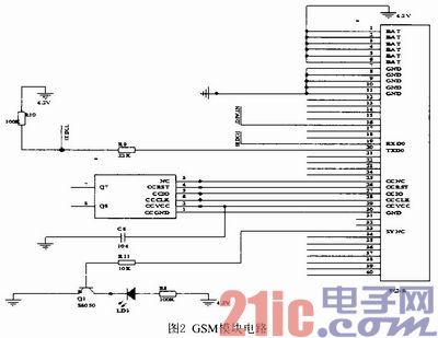
2.2 GSM part This system adopts Siemens GSM module TC35i of Germany. The module is RS232 data port, dual frequency (GSM900/GSM1800), and complies with ETSI standards GSM0707 and GSM0705. It contains RF circuitry and baseband, and provides a standard AT command interface for bidirectional transfer of instructions and data, and fault recovery and restart via shutdown or AT commands. Its working voltage is 4.2V, and it will automatically shut down when the module's power supply voltage is lower than 3.3V. Because the module emits a signal with a current maximum of 2A, it is powered by a high-demand power supply. This system uses the voltage regulator chip LM2941CS, which is dedicated to the adjustable switch type high performance microwave circuit, which can provide stable high current and voltage output. The TC35i module pins can be divided into five categories: power supply, SIM card, data input/output, audio interface and control. When using the TC35i module, to put the TC35i into operation, ensure that its start pin IGT plus a low level longer than 100ms.
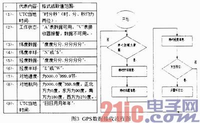
2.3 GPS part The system adopts SIRF third-generation high-sensitivity leaded GPS receiving module SIRF starIII. The chip is serial communication, baud rate 4800; level data output, format is TTL. With 20 channels, it can track 20 satellite channels at the same time, ensuring the highest receiving sensitivity and positioning accuracy less than 10m. There is a rechargeable battery inside, which can store ephemeris data for quick positioning. The data can be powered off for more than seven days. The module GPS uses a standard MMCX antenna interface for easy connection to a GPS antenna. The data line interface uses a 6-wire connector lead output to facilitate prototyping during product development, and is very simple to use, requiring only three output lines. The output of GPS uses the second pin, which is the serial port TTL level signal, the high level is greater than 2.4V, the low level is less than 0.4V, the output drive capability is 2mA, and can be directly interfaced with the single chip; Six feet, each output a pulse signal of about 0.2V with a width of 10ms for timing; the DC positive power supply is 3.5~5.5V, the first pin is used; the fifth pin is used for the power ground. By default, the GPS receiver module SIRF star III outputs positioning data once per second, usually in the $GPRMC streamlined data format. The statement format is as follows:
$GPRMC, <1>, <2>, <3>, <4>, <5>, <6>, <7>, <8>, <9>, <10>, <11>, <12>
*hh
Figure 3 GPS data receiving flow chart
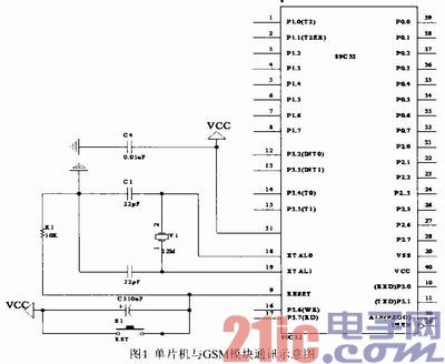
2.4 Control section The control part of this system uses the AT89C52 produced by ATMEL. It is a low-power, high-performance CMOS 8-bit microcontroller with 8k bvtes flash-ready program memory and 256 bytes of random access data memory (RAM). Processor and flash storage unit. The device is manufactured using ATMEL's high-density, permanent storage technology and is compatible with the standard MCS-51 command system. The AT89C52 microcontroller is powerful enough to be used in many more complex control systems. This machine has two full-duplex serial communication ports, which can meet the requirements of simultaneous communication with GSM module and GPS module. The 10 pin and 11 pin of the MCU communicate with the GSM module. The 16-pin and 17-pin of the MCU communicate with the GPS module. As shown in Figure 4.
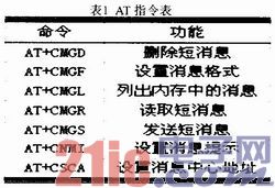
3 AT command MCU can send AT command to control GSM module TC35i, send SMS common text and PDU mode. Text mode is mainly used to transmit GPS information. Text mode is simple and easy to implement, but the disadvantage is that it does not support Chinese text messages. PDU mode is mainly used to send car status and control information. However, the decoding of pure English short messages is inconvenient. Therefore, when sending and receiving pure English characters and numeric characters, the Text mode is adopted. The PUD mode not only supports the Chinese mode, but also can send English text messages.
4 System setup and control The system is built on the basis of reliable and mature GSM mobile network, and makes full use of the resources of GSM mobile network. It uses Chinese short message form to directly display the situation of multiple alarm locations on the user's mobile phone screen. On, to achieve rapid and accurate alarm, real-time. And try to reduce the investment in the user's premises terminal. The user terminal needs to set the GSM service network, the short message special service number, the user mobile phone number, the type and number of the alarm collection module, and the like.
5 Conclusion The main innovation of this paper is that the anti-theft system integrates GSM and GPS. It uses the mobile communication technology of GSM mobile phone module, combined with the popular GPS technology, and cooperates with the single-chip control technology to adopt the most intuitive Chinese short message form. It can directly reflect the situation of multiple alarm locations on the mobile phone, complete the design of the car anti-theft positioning system, and realize the intelligent and safe remote monitoring of the vehicle. According to the specific requirements of vehicle intelligent anti-theft, the system can also upgrade software and hardware. The use of wireless network technology between modules increases the privacy of the system and reduces the possibility of complete destruction of the system. After further improvement, it can be combined with the mobile phone positioning system software, which is convenient for users to use, and is suitable for mass production and promotion.
Features: LED copper wire lamp has advantages of small size, light weight, low power consumption, long service life, low heat and environmental protection, etc.Copper wire lamp softness is high, can moderate bend, make any shape and not easy paragraph.
2. Specification: WIRE COLOR: SILVER, GOLD, COPPER, LED COLOR: WHITE, WARM WHITE, BLUE and MULTICOLOR, RGB.
Wire color:Silver,Gold,Copper. Fuction:Steady,chasing,Flashing,Timer.
Spacing between each bulb:5M,7.5CM,10CM.
POWER SUPPLY: BARRERY BOX, Electronic Transformer.3. Purpose: indoor & outdoor use.LED copper wire lights are not only used for Christmas lights, but also for home decoration and city lighting projects and various entertainment venues.(for example, using range: can be DIY all sorts of strange new and practical products, such as clothes, backpacks, shoes, gloves, hats, jewelry (necklace, lei), bicycles, motorcycles and all kinds of car shine.
String Lights
String Lights,LED String Light,Christmas Light,LED Outdoor String Lights
Heshan Jianhao Lighting Industrial Co., Ltd. , https://www.sunclubtw.com