Foreword
In the industrial industries of metal melting, bending, hot forging, welding and surface heat treatment, induction heating technology is widely used. Induction heating is based on the principle of electromagnetic induction. It uses the heat generated by the eddy current in the workpiece to heat the workpiece. It has high heating efficiency, high speed, good controllability, easy to achieve high temperature and local heating, and easy to realize mechanization and automation. With the development of power electronics and power semiconductor devices, the basic topology of induction heating power supplies has been continuously improved, generally consisting of rectifiers, filters, inverters and some control and protection circuits. The inverter plays an important role in the induction heating power supply. According to the characteristics of the inverter, the inverter power supply is divided into two types: series resonance and parallel resonance. In this paper, a parallel resonant inverter power supply design scheme for induction heating is proposed, which is analyzed and designed for its main circuit, chopper circuit and inverter control circuit.
Circuit composition and design
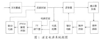
The system block diagram of the power supply is shown in Figure 1. The three-phase AC voltage is converted to a DC voltage after being controlled by the rectification and filtering circuit. The voltage is sent to the DC chopper for chopper regulation and becomes a power-adjustable approximate constant current. After the source is input to the inverter, then the induction heating load is controlled. The DC chopping control part detects the current signal of the chopping output through the sensor, and controls the output pulse width of the PWM through the PI regulator, thereby changing the magnitude of the chopping output current and realizing the closed-loop control. The inverter control part uses the phase-locked loop frequency tracking circuit to control the operating frequency of the inverter, generates a high-frequency trigger pulse, and drives the on and off of the power device in the inverter circuit.
The main circuit of the main circuit 1 and the parallel resonant inverter power supply is composed of a three-phase uncontrolled rectifier bridge, a DC chopper, a current source parallel resonant inverter and a load matching circuit (Fig. 2).
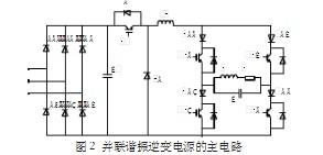
Here, the unregulated rectification plus chopping wave is used to form a DC current source, mainly considering the advantages of fast protection speed and small filter size caused by high frequency chopping. The main power devices (VT and VT1, VT2, VT3, VT4) in the chopper and inverter use IGBT tubes. A diode is connected in series with each IGBT of the inverter bridge arm, and the forward current through the IGBT will also pass through the series diode. This requires the series diode to pass a large forward voltage and withstand a high reverse voltage. Therefore, VD1~VD4 is a quick recovery diode. The inverter switches regularly through the semiconductor switch, and obtains a certain frequency of alternating current on the load side. The frequency is determined by the operating frequency of the switch. Since the current source is supplied, the output current of the inverter is approximately square wave, and the load is applied to the fundamental wave. The component is high-resistance, the voltage drop is large, and the voltage drop generated by the harmonics of three or more times is small, and the output voltage (that is, the voltage across the capacitor C) can be approximated as a sine wave.
2, PWM chopping control
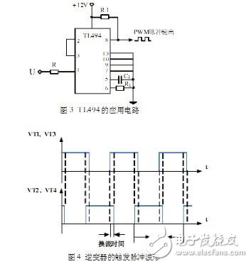
The implementation of chopping is to control the magnitude of the current by controlling the conduction of the IGBT (VT tube in Figure 2) to indirectly control the power. In the steady state operation, in order to understand the change of the load in real time, it is necessary to feedback the change of the current from the resonant circuit, and obtain the duty ratio by comparing with the reference value. The current detection in the system block diagram of Figure 1 can use the Hall current sensor to detect the input current of the inverter DC bus. The control circuit adopts a PI regulator, which is composed of an op amp, a resistor, a capacitor, etc., and can compare the detected current with the set current. As long as the feedback and the setting are deviated, the feedback can be adjusted to approach the set value until it is equal to Set the value to achieve no-difference adjustment and improve system stability. PWM pulse width control uses TL494, which is a widely used PWM control chip with strong anti-interference ability, simple structure, high reliability and low price. In this design, the specific circuit is shown as in Fig. 3: input (ie PI regulation output) is introduced from pin 1, pin 13 is connected to low level, PWM pulse signal is output from pin 8, and the chopper component is triggered by the drive module amplification. IG- BT conduction.
3, inverter trigger control
In the trigger control of the parallel resonant inverter, in order to avoid a large induced potential on the large inductance Ld, the current must be continuous, so to ensure that the inverter is in the commutation, the two sets of bridges VT1, VT3 and VT2, VT4 The principle of first turn-off and turn-off should be followed, that is, the trigger pulses of the two sets of bridge arms are required to have overlapping regions, which is quite different from the series resonant inverter. Figure 4 is the waveform of the inverter trigger pulse.
PDU Power Socket
PDU Power Socket be with any type plug,could be selected to be with USB ports,Internet ports,Phone ports,overload protection and with or without switch.
PDU Power Socket can be set into furniture and office furniture like table,cabinet and so on.It will be easily to use the charging for Phone and home appliance.
Specifically, We have our own design and production team for USB Circuit Board design and produce
PDU Power
PDU Power,Us PDU Power Strip,PDU Power Outlets,United Power PDU
Dongguan baiyou electronic co.,ltd , https://www.dgbaiyou.com