0 Preface
Short-wave All broadcasts have large coverage, long transmission distance, simple receiver and low price, and have been used as the preferred technical means of information dissemination in countries around the world. Due to technical limitations, the singularity of traditional AM broadcast programs is subject to inherent transmission interference caused by ionospheric changes and frequency selective fading, and the disadvantages of low listening sound quality are more prominent. In order to digitize AM-band analog AM broadcasting, DRM (World Digital Broadcasting Organization) has established a universal digital AM broadcasting standard with countries around the world and promoted digital AM broadcasting technology.
1 system overall design
The short-wave DRM communication system includes four parts, a human-computer interaction interface, a source part, a channel part part, and a transceiver part. The overall design block diagram is shown in Figure 1:
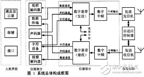
1.1 Human Machine Interface Section
The human machine interface part is composed of a liquid crystal display and a button. A set of buttons is placed next to the LCD display, and the corresponding parameters are input through the buttons. The human-machine interface uses a low-cost and simple peripheral MCU to complete the screen control and button detection, and sends the results of the settings and changes to the single-board computer.
1.2 source interface part
The source interface part supports integrated service terminals, computers or audio and video codec devices. In order to meet the needs of different services, DRM shortwave communication system provides three kinds of service source interfaces:
(1) Data channel One-to-one data terminal can be a computer, an integrated service terminal (such as 802), a video or audio compression coding device, and the like. This channel provides maximum transmission capacity to meet the needs of data communication.
(2) The vocoding channels can be connected to various vocoding devices. The channel can be switched at 4.8, 3.6, 2.4, 1.2, and 0.6 Kbps depending on the traffic of the audio data compressed by the different vocoders. This channel can be turned off when not in use to provide the largest possible data bandwidth for the data channel.
(3) Character channel one ~ can connect to various character transceiver devices (for example: running HyperTerminal program on a computer). The channel has a speed of only lOObps, and the purpose is to provide an information channel for communication parties to communicate instantly. For example, a short message service.
All source devices are multiplexed with one LAN port. The distinction of services is implemented in the network port control program on the single board machine. The source interface part is responsible for communicating with the source device to obtain information of the source device, and interacting with them to implement flow control and state control functions.
1.3 channel part
The channel part is the main body of this research and development, which is mainly composed of a baseband part and a digital up-conversion part.
1.3.1 Digital baseband section
The digital baseband part completes the processing of the source information so that they are suitable for transmission on the wireless channel, have certain anti-burst interference, anti-error capability, and match the transmission capability of the wireless channel. Divide it into the following three parts:
(1) Multiplexing process and demultiplexing process: In order to realize synchronous transmission of three services, data of three kinds of services needs to be multiplexed into one multiplexing frame. The multiplexing process needs to calculate the length of the multiplexed frame according to the current configuration, and allocates a bit rate for three services according to the certain priority according to the length; in order to smoothly receive and demultiplex the receiver, a FAC is generated at this time. Channel data and SDC channel data.
(2) Channel coding and decoding part: encodes the data of the MSC, FAC and SDC channels. Energy diffusion is performed to reduce the possibility of continuous O or l occurrence; code stream partitioning of MSC channel data is performed to hierarchically protect services required for different error protection, and hierarchical coding and coding are performed at different levels according to the result of code stream partitioning. Convolutional coding code; bit interleaving operation is to interleave bits in the hierarchical coding region to increase the system's ability to resist burst errors; according to user requirements, the bits are QAM mapped according to a specified constellation; (3) OFDM modulation and demodulation: In this part, pilot data is generated, the superframe is transmitted, and the frequency domain to time domain transform operation is performed. For reception, a synchronization process is also performed to regain the superframe. The synchronization process of the system should be the core technology digital baseband in the system through the USB2.0 and digital intermediate frequency system data and control transmission. After the organization, the transmission superframe and control information are organized and transmitted to the digital intermediate frequency, which is further processed by the digital intermediate frequency.
1.3.2 Digital intermediate frequency
The core device of the digital baseband is an FPGA. In addition, a single-chip microcomputer implements USB2.O communication and control functions.
(1) Digital up-conversion: The baseband signal is converted into a radio frequency signal suitable for the transmitter.
In order to be able to connect various active short-wave radio channel equipment, the DRM short-wave communication system has an IF output frequency range of 0.1'5MHz and an output amplitude of -18'+ldb. (2) Digital down-conversion: transforms the receiver's IF signal into a suitable one. Baseband signal processed by digital baseband. In order to be able to connect various active short-wave radio channel equipment, the DRM short-wave communication system has an intermediate frequency input frequency range of 12'500KHz and an input amplitude of -35~|5dbm.
1.4 transceiver part
Transceivers can use a variety of shortwave transmitters and shortwave receivers.
Because the short-wave DRM communication system provides an orthogonal frequency division multiplexing signal with a bandwidth of 4.5'20KHz, it cannot pass through the audio interface of the transceiver (the audio interface bandwidth limitation of the transceiver is generally 300'3000Hz, only 2.7KHz bandwidth ), can only be connected through the transceiver's IF port. In order to ensure that the IF connection is not affected by the connection line, a connection box is installed in the transmitter and the receiver to isolate the external line.
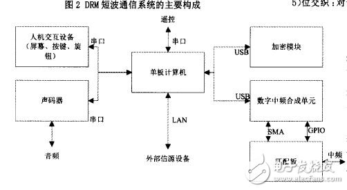
2 hardware components
The hardware of DRM short-wave communication system is composed of human-computer interaction board, single-board computer and intermediate frequency synthesis unit and encryption module, as shown in Figure 2. The human-machine interface part is responsible for displaying the status and receiving control input; the single board machine performs the entire channel codec and modulation and demodulation processing; the digital intermediate frequency synthesizing unit performs digital up-conversion and digital filtering to generate an intermediate frequency signal. The vocoder is a purchased part for voice coding; the cryptographic module is used for special communication.
2.1 Human-computer interaction equipment
The role of the human-machine interface part is to set the mode of operation of the device, including control of parameters such as bandwidth, channel adaptation mode, interleaving, QAM modulation, channel coding rate, and vocoding, and also displays the current state. The man-machine interface device is a printed board i screen, buttons, buzzer, and single chip fixed on a printed board, and the printed board is fixed on the front panel of the chassis.
Led Parking Light,Parking Lot Lamps,Outdoor Led Parking Lot Lights,Commercial Parking Lot Lights
Changxing Fanya Lighting Co.,Ltd , https://www.fyledlights.com