Ultra-long-range high-fidelity reception of FM broadcast
The reception of FM broadcasts has been a hot topic in recent years, especially last year. This is because FM broadcasts have better sound quality, higher fidelity, stronger anti-interference, and richer programs than AM broadcasts. The most critical It is low cost, although digital audio sources are everywhere, such as CD, VCD, DVD, etc., but the cost is high, the music software is an endless expense, and the reception of FM radio programs is free, so it is not rich in income For many audiophiles who want to enjoy music, listening to FM stereo (FM ST.) Radio programs is undoubtedly the best choice. But the pursuit of audiophiles is endless. The more stations you receive, the greater the selectivity, but local radio stations are limited after all. This is the origin of FM remote reception.
I am also a member of FM enthusiasts. I have been fond of FM reception for more than ten years and have summarized some experiences. In the "Electronic News" a few years ago, some articles about FM reception were published. Especially after the introduction of the digital tuning radio for American Dodge cars, it caused a nationwide FM reception fever. At that time, it was due to the weather, geographical conditions, people, and the frequency of FM broadcasts across the country was increasing. Of Shaoyou joined the ranks of receiving. However, things are not as simple as we thought, there are problems of one kind or another. Today, there are still ringing phone calls and there are many letters. Ask me questions such as material selection, reception, maintenance, etc. About, to mention the pen again, the system introduces the relevant knowledge of FM high-fidelity reception and material selection, so that the majority of FM reception enthusiasts can get their wish and realize the dream of FM fever.
A complete set of FM broadcast receiving system consists of two parts, as shown in Figure 1, including outdoor and indoor. The outdoor part includes antenna rack and antenna amplifier; the indoor part includes FM tuner, power amplifier and speaker. The FM receiver is composed of FM high frequency head and mid-range stereo decoding circuit. Each is explained in detail below.
1. Antenna Antenna is the gateway of the receiving system. It is the first stop. Without an antenna, no matter how good the receiver cannot receive the signal, without a good antenna, remote reception is impossible. In order to facilitate everyone's understanding, we compare with TV reception, because everyone is quite familiar with TV reception, and they are both FM transmission. The design of the FM antenna is completely equivalent to the TV antenna. If the requirements are not high, you can directly replace the FM antenna with a 5-channel TV outdoor antenna. The antenna has the following three indicators:
1. Gain The gain of an antenna is an important indicator used to illustrate the ability of the antenna to receive signals. It is determined by the direction angle of the antenna and the front-to-back radiation ratio. The smaller the directional angle, the stronger the receiving capability of the antenna, and the less interference from other directions, which is why the antenna must be aligned in the direction to receive clear images and sound. The front-to-back radiation ratio of the antenna refers to the ratio of the received signal strength before and after the antenna. The larger the value, the better the antenna performance. The basic unit vibrator antenna has two maximum receiving surfaces, that is, the front-to-back ratio is 1: 1. How to increase the front-to-back ratio to make the directivity more sharp, the best way is to add a director and a reverser, which is why A single vibrator is used only when the signal is strong, and the reason for using a multi-element antenna when the signal is weak. Theoretically, the more directors, the higher the gain, and only one inverter is enough, but too many directors will affect the bandwidth, the mechanical strength is also poor, and the installation size is huge, so antennas with frequency bands are generally used Three-element antennas, but no more than five elements.
2. The directional diagram represents the antenna's ability to receive signals from different directions. It has a different meaning from the direction angle. In principle, the signal direction of the half-wave dipole antenna should be perpendicular to the signal of the radio transmitting station, but in fact, the reception of remote signals may have deviations in reception due to changes in propagation. The actual receiving effect should be the best standard. Of course, we require not only one direction, but 360 ° omnidirectional reception, which results in multidirectional and omnidirectional antennas. In fact, the previous single vibrator is a multidirectional antenna. If the two pairs of vibrators are vertically combined, it becomes a cross omnidirectional antenna. This kind of antenna was originally introduced by the author. Weak areas are not very suitable. The only way is to use a steering antenna, which has both high gain and good pattern. It can receive signals from any direction vertically and get the maximum gain. It can improve the signal-to-noise ratio and eliminate adjacent frequencies. Interference or even co-channel interference is the best choice for our FM receivers.
3. Bandwidth It is an indicator of the frequency of the received FM signal. The wider the passband, the more radio stations it receives. China stipulates that the frequency range of FM broadcasting is 87.5 ~ 108MHz, with a total bandwidth of 20MHz. It is still a narrowband antenna, of which _____
The heart frequency is = √λ1? Λ2 = 97.4MHz, generally 98MHz, if it is biased to a certain frequency band, such as the low band (88 ~ 98MHz) or the high frequency band (98 ~ 108MHz), when designing the antenna, you can intentionally lean towards a certain end, Be flexible.
In short, the requirements for receiving an FM broadcast on an outdoor antenna are high gain, omnidirectional reception (or directional reception if there is no radio in other directions), and it is convenient to use. Generally, the gain of a three-element antenna is 7 dB, and that of a five-element antenna can reach 11 dB. The FM9901A antenna used by the author last year was the first three-unit dedicated antenna designed for FM broadcast reception in China. The power box can be used to control the antenna to rotate in all directions and receive good results. Due to the complex calculation of the design antenna size, only the production size of the five-unit FM antenna is given below, as shown in Figure 2, for the reference of enthusiasts.
Material: Use ∮10mm aluminum tube, made according to the picture, copper tube is better, the larger the diameter, the better, but when bending the vibrator, first fill it with sand and then bend it, so it is not easy to break and the bend is smooth. It can be connected with the same material in the middle, but it must be at the midpoint of the director and the reverser. It can also be connected with insulating materials without affecting the effect.
Second, the antenna amplifier amplifier is an indispensable part of FM ultra-long-range reception, without it, ultra-long-range reception is impossible. Its role is to amplify the weak signal received by the antenna to improve the signal-to-noise ratio. In addition, the antenna for long-distance reception is generally set up very high, and it takes a long feeder to be introduced into the room, which has a certain loss. Another function of the amplifier is to make up for the loss caused by the transmission feeder.
An important indicator of the antenna amplifier is the gain. Generally speaking, the gain is higher and the output level is correspondingly higher, but the noise also increases, especially for weak signals. When a strong signal is input, the output level is too high and the receiver will be overloaded and distorted. There is a blocking phenomenon, so the gain should be appropriate, generally around 30dB. It should be noted that the amplifier should not be regarded as a universal weapon. It seems that with the amplifier, all problems are solved. There are many complicated reasons here (to be described later) . Because the frequency band bandwidth is only 20MHz, it is a narrow-band amplifier, as long as the corresponding band-pass filter is added in the front stage.
The principle of choosing an amplifier is high gain, low noise, preferably with AGC function. The early products are composed of two-stage or three-stage high-frequency transistors, and the noise is large; the later products use one-stage low-noise transistor plus one-stage integrated amplifier circuit, the most common form is 2SC3358 + μPC1651, which is used by many manufacturers Optional. In recent years, it is better to use the AT415 + A08 circuit with better performance indicators. The author believes that this is the best combination at present, which meets the selection principle of low noise and high gain. The QG836 amplifier that I once introduced is this form. If there are conditions, an amplifier composed of a two-stage double-gate field effect tube can be selected. In addition to lower noise and higher gain, it also has a strong anti-overload capability. It should be a discrete component except for integrated circuits. The best choice, the double grid tube can choose K73, BF964 and other models.
In fact, as long as it is an amplifier used on TV, it can be used for frequency modulation. Just replace the pre-stage bandpass filter with an integrated BPF dedicated for frequency modulation. Its appearance is like a ceramic capacitor, but there are three Pins, that is, input, ground, output, its role is to filter out signals other than 88 ~ 108MHz, and the FM signal is unobstructed, effectively improving the signal-to-noise ratio. If this item is not available, a combination of inductance and capacitance can be used, as shown in Figure 3.
Let me tell you one more time, I tested the high-frequency head used for satellite reception as an antenna amplifier some time ago and achieved good results. The high-frequency head metal shielded rainproof structure used for satellite reception, its internal mixing stage and local oscillation stage are not used. There is a high-frequency amplifying circuit composed of three-stage field effect tube inside, and its receiving frequency is 3.4 ~ 4.2GHz, which is dozens of times of the tuning frequency band, with high gain and good effect. Although there is a resonant circuit inside, the microstrip inductance is only equivalent to a straight wire for the FM signal. Adding BPF to the front stage is a good amplifier. Of course, the author just did an experiment, the time is not long, and its stability has yet to be tested. 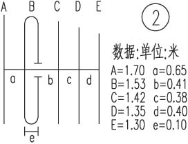
3. Some outdoor systems are connected and installed with good antennas and amplifiers, and their connection is also very important.
1. The connection between the antenna frame and the amplifier is generally speaking, the input and output impedance of the amplifier are both 75Ω, and the impedance of the folded vibrator is 300Ω, and a 4: 1 impedance matcher (300/75 matching on the TV socket can be used) Device substitute) to match. If it is directly connected, the loss will increase, and the already very weak signal, if there is any loss, the signal will not be smaller, so it should pay great attention to the matching problem. Although the impedance of the half-wave vibrator is 75Ω, its mechanical strength is poor, and there is also a 1: 1 balanced unbalanced matching problem with the 75Ω coaxial cable. The transmission line does not use a flat feeder but a round feeder because the former has too much loss, so a 75Ω coaxial cable with a smaller loss is used. Generally, the 75-3 type is used, and 75-5 is better. Of course, the cost is higher. The antenna amplifier is generally installed at about 30 cm below the antenna frame, and it is also integrated into an integrated form. For example, the FM9901 antenna is this form, and it also solves the problem of rain and snow.
2. The connection from the amplifier to the receiver If the receiver is a single whip rod antenna, only the middle copper wire of the coaxial cable is connected, and the outer shielding net is empty. If it is a finished tuner, there are generally two sets of antenna input terminals of 75Ω and 300Ω, which can be connected to the 75Ω terminal of the crimping method. Only with correct matching can the maximum level input be obtained.
If an outdoor antenna is erected, the height of the antenna should be increased as much as possible, generally 6m above the ground and 3m above the roof. But it is not the higher the better, the effect may be worse if it is too high. The height should be determined according to the actual receiving effect. If the surrounding objects are not as high as the antenna, a lightning rod should be installed and grounded to avoid lightning strikes.
Many readers inquired by phone or letter: According to the introduction, a certain type of antenna or amplifier received good results, but why the actual use was not improved, or the effect was worse. It should be said that the equipment is good, but it is also relatively speaking. This is related to the method of use. May wish to check whether there is a problem with the system connection. Secondly, the quality of the receiving effect also has a great relationship with the surrounding environment, such as the height of the transmitting station antenna, the size of the transmitted power and the surrounding buildings, etc., cannot be generalized. Generally speaking, reception in mountainous areas is worse than in plains, especially ultra-long-range reception. Sometimes moving the antenna position a few meters and trying a few more points to set up may make a big difference. If you can use the outdoor antenna to receive the broadcast, there is no need to add an amplifier. If the amplifier is not used properly, it is a noise source; some in order to achieve remote reception, two amplifiers are connected in series. At this time, you must pay attention to the distance between the two amplifiers. 2m, there must be some attenuation, otherwise it is difficult to succeed.
I am located in the mountainous area of ​​Heilongjiang (44.7 ° north latitude, 128.2 ° east longitude). I have received dozens of radio stations using a cross omnidirectional antenna in conjunction with a Dodge machine or a galaxy machine. Good results include Harbin ’s third set of provincial and provincial broadcasts, Changchun ’s eighth set, and Jilin ’s fourth set, and the rest are neighboring counties and cities. However, other cultural stations such as Beijing, Anhui, Wuhan, Hubei, Jiangsu, and Zhejiang, as well as foreign stations such as South Korea, Japan, and Russia are all ultra-long-range receivers. Such stations cannot be received stably for a long time because they are ionospheric. The field strength formed by refraction and reflection suddenly increases and decreases, and it will be stable and clear for a while, and noise will rise again until it disappears. The general rule is: morning and evening reception is good, summer is better than winter.
4. The sensitivity of the FM high-frequency head FM receiver is mainly determined by the high-frequency head. It is the first station of the receiver. In general, discrete components are better than integrated circuits, and two integrated circuits are better than single-chip circuits. For example, CXA1238, CXA1019, TEA5711, etc., which are common in the market, are all monolithic radio circuits, integrating high amplifier, middle amplifier, demodulation (even power amplifier). Because the circuit is crowded on a chip, there are bound to be some trade-offs. The monolithic FM head circuit, such as TA7358, LA1185, etc. are dedicated FM head circuits, so the consistency is better and the sensitivity is higher. It generally includes three parts: high amplifier, local oscillator, and mixing, so a dedicated FM head is used. The circuit plus the intermediate amplifier demodulation circuit should be a better combination, such as the common TA7358 + TA8132, Desheng PL757, etc. The FM heads assembled in discrete parts were all triode circuits in the early stage, with first-level high-amplification and first-level frequency conversion, preferably with independent local oscillators. If the high-amplifier transistor is replaced with a field effect tube, the noise is greatly reduced, and the gain can also be increased by a few decibels. If you want to further increase the gain, simply increasing the number of high-amplifier stages is not enough (so the noise is also large), you must use a narrow-band tuning circuit, that is, add a frequency selection loop before the high-amplifier stage, which not only improves Gain, and improve the anti-interference ability and selectivity, so the advanced FM head uses three-connected variable capacitor tuning, such as the high-frequency head of the car's FM radio uses this three-connected variable capacitor or inductance tuning, high The amplifier uses a single-gate field effect tube, which has independent local oscillator and mixing frequency, which is why the radio on the car is more sensitive than the ordinary radio. For the car radio circuit, please refer to the appendix of the 1991 edition of this newspaper. The sensitivity of the tuner is expressed in μV. Generally, the sensitivity of ≤1μV is a very good index.
Regarding the digital tuner (electrical tuning), it is just to change the variable capacitance of the tuning station to a varactor diode, and to change the voltage applied to the diode, the capacitance also changes accordingly. This eliminates the need for larger capacitors and complicated wire-drawing mechanisms, and can add key control and remote control, which is much more convenient. Electrically tuned receivers generally have a liquid crystal (or fluorescent) display screen, which is used to display band, frequency, time, stereo, station number and other information to make the reception clear. Now digital tuners have dropped from a few hundred yuan to one or two hundred yuan. FM receiving enthusiasts are best to use this digital tuner, especially the high-frequency head assembled by three varactor diodes, but do not think that digital tuning The sensitivity of the device is high, but it is just convenient to use. The US Dodge car radio introduced last year and the domestic Galaxy 883A tuner both use narrow-band tuning high-frequency heads, so the sensitivity is very high, but unfortunately there is currently no goods available. The author introduced two high-performance FM high frequencies in the 10th issue of this newspaper this year, both of which are brand new Japanese originals, with independent shielding, field effect amplification, and narrowband tuning electric tuning dedicated fever heads. The special feature is that it is divided into three sections , Frequency range VL: 70 ~ 150MHz, VH? 176 ~ 223MHz; U segment: 475 ~ 770MHz; In addition to receiving standard FM band, it can also receive the sound of TV channels above 3, including most of the supplementary channels, is not much Very good FM broadband receiver.
In addition, the author recommends a circuit with very good performance, see Figure 4, for enthusiasts to make their own reference. This is a discrete and integrated FM high-frequency head. It combines the advantages of the two: one-stage double-gate field effect tube is tuned and amplified, and then enters the FM high-frequency head special integrated circuit AN7254 after the frequency selection network. High-amplifier, mixing output intermediate frequency 10.7MHz signal, and then through 10.7MHz filter into the FM mid-cycle for further frequency selection, enter the integrated circuit for pre-amplifier, output pure intermediate frequency from ⑨ pin, and then 10. After 7MHz filtering, it is sent to the middle amplifier for demodulation. Through the above simple process description, it can be seen that the 10.7MHz intermediate frequency signal has been subjected to three-stage filtering, which can be described as pure and pure, and its selectivity and sensitivity are excellent. What is more rare is that in addition to its conventional functions, the AN7254 has its It also outputs the high-amplifier AGC voltage and regulates the second grid of the double-gate tube to achieve the purpose of automatically controlling the high-amplifier gain and avoid the blocking phenomenon caused by high sensitivity encountering strong signals. The author believes that this is the best FM high-frequency head circuit. 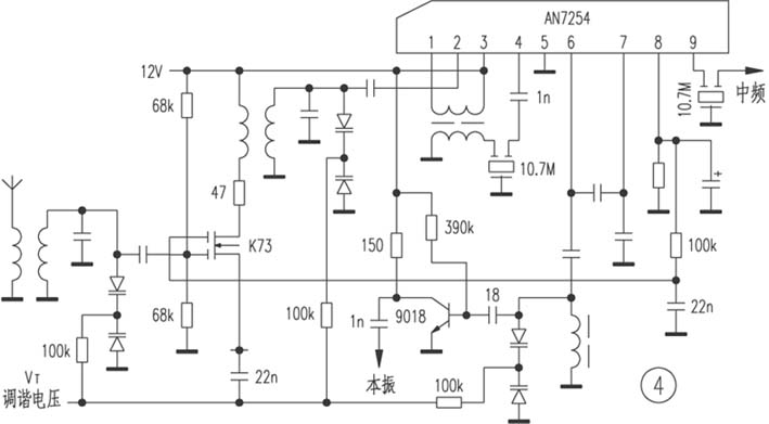
Fifth, with the high-frequency front-end high-frequency head, it only shows that it has the ability to receive ultra-long-range weak signals.
How to demodulate the IF signal and restore it to sound to achieve high fidelity is an important and often overlooked step. This part of the circuit is composed of amplifier, demodulation, and stereo decoding circuits, with tuning instructions and stereo instructions, and single / dual sound switching circuits. The main technical indicators are: intermediate amplifier gain, the higher the better; the harmonic distortion, the lower the better; the signal-to-noise ratio, the higher the better; the stereo separation, the higher the better. This part of the circuit is mainly composed of integrated circuits. Commonly used circuits are CX-A1238, TEA5711, TA8127, TA8132 and so on. These circuits, as long as the 10.7MHz intermediate frequency signal is input, there will be a stereo audio signal output of the left and right channels, and these circuits can be equipped with AM circuits, few peripheral components, suitable for your own production, other two circuits For example, if the demodulation of the middle amplifier only outputs the mono signal, it also needs to enter the single-chip decoding circuit. It is not as simple as a piece, and the performance is stable.
The author recommends the M51535 circuit of Mitsubishi Japan. The application circuit diagram is shown in Figure 5. This is the single-chip demodulation circuit with the best performance indicators I have seen so far, especially the selection of peripheral components, and make full use of supplements: CBB capacitors, black diamond electrolysis, Murata porcelain, TDK 10.7M. Trials have shown that the sound after demodulation is quite good, and it is no exaggeration to call it high fidelity. This makes me think: today, when stereo motors are popular, why not take a high-fidelity sound source of your FM tuner? Not much cost, there may be unexpected gains! The technical specifications of the circuit are: harmonic distortion of 0.05%, signal-to-noise ratio of 72dB, stereo separation of 45dB, which shows good performance. But there are only stereo instructions and no tuning instructions, and the above models all have tuning and stereo instructions. In addition, stereo broadcast programs receiving weak signals are noisy. However, there is an automatic switching circuit inside the circuit, and the manual switch can also be used to directly switch to the mono position. At this time, it becomes a clear mono broadcast. The principle is to reduce the bandwidth and improve the signal-to-noise ratio, because the radio frequency refers to its carrier frequency, and there are 200kHz sideband signals above and below it, so the two stations will be separated by 0.4MHz, and interference will not occur, mono The channel broadcast bandwidth is 200 kHz and the stereo bandwidth is 400 kHz. In fact, when receiving broadcast programs, due to the small number of local stations and the large distance, it is impossible to produce interference, and it is inevitable that when receiving a lot of remote stations, there is adjacent frequency or co-frequency interference, except that the direction of the antenna is eliminated In addition, when interference occurs at 0.3MHz intervals, two 10.7MHz intermediate frequency ceramic filters can be used in series to suppress adjacent frequency interference, and generally good results can be achieved. At this time, it is best to use a first-level pre-amplifier to compensate for the insertion loss of 10.7MHz. For details, please refer to the relevant articles in the 1997 edition of this newspaper.
The configuration of the speaker and the power amplifier is beyond the scope of this article, but the received FM program still has noise. The noise reduction circuit of the power amplifier can be used. It is generally assembled with LM1894. It has a good effect on suppressing FM broadcast noise. Used in series, the noise reduction effect is doubled. If there is no such circuit on the power amplifier, it may be directly added to the tuner to become a true high-fidelity tuner. The following recommends a golden combination: a three-unit remote steering outdoor antenna with antenna amplifier dedicated FM antenna + TV remote control board + MITSUMI three-band FM head + M5135 mid-range stereo decoder board + LM1894 noise reduction circuit, the total cost is about 320 yuan. With this combination, it can be described as a super high-sensitivity full-band FM tuner. It can store up to 90 radio stations and realize the reception of FM signals from 70 to 770 MHz. Everything is selected by the remote control. The structure of the Mizmi three-band high-frequency head is very similar to the color TV high-frequency head, so it is very convenient to directly use the TV remote control board with a remote control installed (if the remote control board is omitted, the cost can be saved, but hand tuning is too troublesome. Must be tuned with a dedicated multi-turn potentiometer). If you add a TA7630 board, you can also remotely control the high and low bass, balance, and volume; if you add an ESC AM component (receiving frequency 0.1 ~ 6MHz), you can listen to long, medium, and short waves. AM radio station, of course, the cost has increased accordingly, but after all, for every penny, the overall price is still very high.
The above is a little experience written in combination with my receiving experience. If your conditions are good, you can receive radio programs transmitted by satellite, it is also FM system, its sound quality reaches CD level, but can not be demodulated with ordinary radio, but a dedicated satellite receiver. At present, a set of 1.5m analog sets is only four or five hundred yuan, and a set of digital kits is only more than one thousand yuan, which is much cheaper than previous years. Its reception effect is very stable, without any interference, and broadcast 24 hours a day. At present, more than a dozen sets of central and provincial broadcast programs transmitted by sound subcarriers can be received in the analog suites (some programs need to be decoded by the Liyin decoder), while the digital suites can receive four on Asia 2 satellites only. Fifty sets of radio programs, including some foreign music stations, are mostly stereo, and the sound quality is quite good. At present, domestic programs are all concentrated on the Xinnuo-1 satellite. Although the images are encrypted, the broadcast programs are still open. Among them, there are 7 sets of the Central People ’s Broadcasting Station, 1 set of China International Radio, and the third set of the central literary FM is stereo. There are more than 30 sets of programs, and it only takes a 0.6-meter antenna to receive this satellite signal, which is a popular project in the country. Not only can we see an approximate DVD picture, we can also hear CD level sound and broadcast, and the key signal is very stable. Of course, there is also a satellite dedicated to audio broadcasting, Asia Star, which has now been successfully launched and targeted, but the receiver is too expensive and we cannot afford it at present. Originally, digital receivers were used to watch digital TV programs, but now we use it as a radio, which seems to be overkill, but as a high-quality audio broadcast program, it is a good attempt. 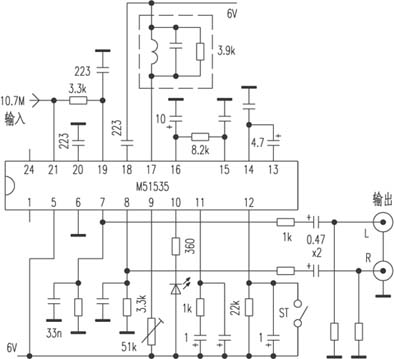
We are the China leading Agents and suppliers of Medical Epidemic Preventive Materials, such as Medical Infrared Thermometer, forehead thermometer, Infrared forehead temperature detector, Infrared temperature tester,Infrared temperature instrument
We are specialized manufacturers from China, Infrared Thermometer, Medical Materials suppliers/factory, wholesale high-quality products of medical Epidemic Preventive materials R & D and manufacturing, we have the perfect after-sales service and technical support. Look forward to your cooperation!
Medical Infrared Thermometer
Medical Infrared Thermometer, forehead thermometer, Infrared forehead temperature detector, Infrared temperature tester Infrared temperature instrument
Shenzhen Daceen Technology Co., Ltd. , https://www.daceen-sz.com