It is undeniable that semiconductor technology has made great progress in the past period, but there are still many audiophiles who insist that the sound performance of the tube is better.
Although the tube needs a separate filament heating power supply and high-Voltage power supply, compared with solid-state devices, the tube still has many advantages that its semiconductor rivals do not have. Therefore, it is completely understandable that audiophiles still have a special liking for tube amplifiers. Why use a tube?
First, tubes are easy to inspire. In the low frequency band, the impedance of the electron tube grid and the cathode is as high as 100Mfl, and it does not have a large parallel capacitance like VMOS. At the same time, the consistency of the electron tube is good. In the same batch of products, the matching between the electron tube samples is much better than that of the transistor. Therefore, using a tube to make an AB output stage may be much more linear than using an equivalent solid-state device. It can be asserted that the tube will never disappear in the near future, especially in the audio field.
Out of an exploration psychology, we used a pair of EL34 tubes that were widely used before and driven by solid-state circuits.
We think that using EL34 as the output tube is the best choice. The reasons are: first, EL34 has a plate dissipation of up to 25W. At the same time, it can be installed on the cheaper standard eight-pin locking tube seat. As for the use of solid-state drives, you will gradually understand in the process of reading this article. Now let us first study the basic situation about the output stage.
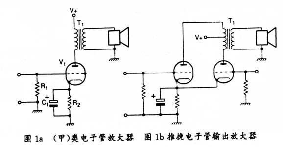
The simplest form of the tube output stage is a single-ended Class A triode amplifier, as shown in Figure 1a). Because the electron tube has limited capacitive current and considerable internal resistance, the plate driving voltage is directly applied to the speaker through an impedance matching transformer. This type of system works well, but its theoretical maximum efficiency is only 50%. Usually because of the limitations of the plate characteristics, the actual efficiency is mostly around 25%. In this way, the output stage of the single-ended transistor seems to have become the yellow flower yesterday. However, audiophiles brought it back to life. If you are economically ambitious and interested, you can purchase a special triode tube amplifier at a high price, which requires 30,000 pounds in the UK.
Tube output stage
The general tube output stage is shown in Figure 1b. For simplicity, the tubes are represented as transistors. The output is fed from the plate of the electron tube to the primary of the output transformer. The center tap of the primary winding is connected to the positive power supply.
When the in-phase and inverted input signals are applied to the gate of the electron tube, a push-pull effect is obtained. For solid-state devices, this type of operation depends on the bias current.
The push-pull stage usually has the advantages of canceling even harmonics and increasing output power. In addition, the noise voltage on the plate can be eliminated, and the ripple of the high-power power supply can be suppressed.
Use EL34 in this kind of circuit, add appropriate high voltage, can obtain the power output of 20-50W. However, the main design task of the output stage of the tube is to output the transformer, especially to ensure a good frequency response, but also depends on the elaborate design of the output transformer.
The area of ​​actual transformers and theoretical models. In addition, the former needs to consider making the primary inductance large enough to obtain a good low-frequency response. Similarly, at the high end of the frequency band, leakage inductance and winding capacitance limit the high frequency response.
The circuit model of an actual transformer is shown in Figure 2, where Figure 2a is a low-frequency equivalent circuit. The components in Figure 2 are: r1 is the primary resistance, L1 is the primary leakage inductance, r2 is the secondary resistance, and L2 is the equivalent secondary Level leakage inductance, R0 is the equivalent iron loss resistance, L0 is the primary inductance, C1 and C2 are the equivalent concentrated capacitance of the primary and secondary, Cw is the inter-turn capacitance, and RL is the secondary load. Here, the primary inductance and the plate impedance of the electron tube form a high-pass filter. Obviously, the larger the primary inductance, the better the low frequency response. In Figure 2a, the Rp plate resistance, Rw is the winding resistance, L0 primary inductance, and RL is the square of the secondary load times the turns ratio.
Figure 2b shows the high-frequency equivalent circuit of the transformer. In the high frequency band, the primary inductance is large enough to have no effect on the frequency response, but the leakage inductance Lk winding capacitor C together forms a second-order low-pass filter.
Leakage inductance and winding capacitance both depend on the structure of the transformer. In order to reduce the influence of these two factors on the frequency response, the winding of the transformer usually adopts the segmented winding method + It can be clearly seen from the equivalent circuit that in order to obtain a good high-frequency response, the leakage inductance must strive to minimize.
When the plate resistance is given, and when calculating the required primary inductance, it can be seen that the lower the plate resistance, the required primary inductance also decreases sharply. In fact, if the output impedance can be zero, then the required primary inductance can also be zero. Similarly, it can be proved that the distortion introduced by the transformer depends to a large extent on the plate resistance. If zero-impedance driving can be achieved, the distortion will be reduced to zero.
Therefore, the triode output stage is preferred in a device because the triode tube has a lower plate impedance than the pentode. Therefore, for a given low frequency response, the primary inductance necessary for the output transformer of the transistor can also be low. Most practical designs use deep negative feedback to reduce the effective plate resistance.
Generally, the feedback is taken from the output winding of the transformer, that is, the secondary winding is included in the feedback loop. However, because the output transformer has reactive components, the amount of feedback that can be introduced in this way is usually strictly limited to avoid parasitic oscillations. 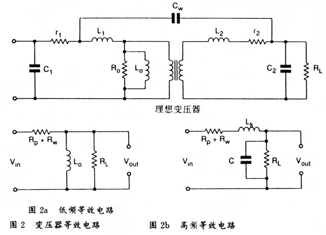
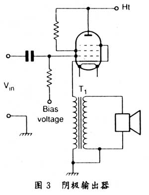
The best way to solve this problem is to use a cathode output stage, as shown in Figure 3. This circuit has a similar function to the emitter output that is familiar to everyone in solid-state circuits. Its voltage gain is always less than 1, but its output impedance is much smaller than that of a triode amplifier that is usually cathode-grounded. The distortion is usually an order of magnitude smaller.
Due to the above limitations, the cathode output device is more used in laboratory occasions, because driving such circuits almost needs to give double the signal amplitude within the range allowed by high voltage, but before developing the practical circuit described below, A push-pull cathode output device has been tested, driven by an inter-stage transformer (inte_stagtransformer). However, there is another way to produce the same effect as a cathode output device. It has all the advantages of a general tube output stage with few side effects. This circuit is a combination of transconductance (transconductance) amplifier and transresistance (transresistance) amplifier, as shown in Figure 4.
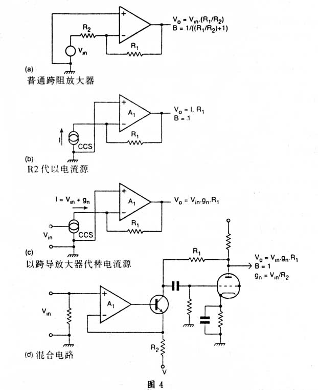
It is difficult to understand why this unique circuit has not been widely used. Because this type of circuit can achieve good performance with a small number of components. Figure 4a shows a transimpedance amplifier that works like an ordinary virtual ground amplifier.
If the open-loop gain is high, the closed-loop performance is determined by the ratio of R1 and R2. If R1 is replaced by a constant current source, then we get Figure 4b. This amplifier can "see" 100% negative feedback at its inverting end, and its voltage gain is zero.
To replace the constant current source with a transconductance amplifier, the output of the amplifier is IK1, and the distortion generated by the transimpedance stage is very small, because the feedback coefficient p (signal feedback ratio) is almost 1. Because the transconductance amplifier can also be made into unity gain, a circuit with excellent performance can be obtained.
In the current circuit, the transimpedance amplifier consists of a tube. The transistor in the feedback loop of the TL072 op amp is the basis of the transconductance amplifier. In the entire audio frequency band, the output impedance given by this circuit is greater than 10MI. The required voltage gain can be obtained by changing the transconductance ratio R2, and the voltage gain of the transconductance amplifier and the transimpedance amplifier are both 1. The well-balanced push-pull output from the drive circuit also needs to drive the push-pull output stage. To this end, the inverting input of the op amp can be easily driven to the push-pull output stage via a resistor and a DC blocking capacitor.
Figure 4 summarizes the entire design idea. Figure 4a is a transimpedance amplifier for a common working virtual circuit. Figure 4b is a circuit that replaces resistor R2 with a constant current source. Its inverting input has 100% negative feedback and voltage gain Is zero. Figure 4c is a circuit that replaces the constant current source with a transconductance amplifier. The feedback coefficient p is approximately 1 and the distortion is very small. Figure 4d converts Figure 4C into a hybrid circuit with a tube.
With the foundation of the circuit in Figure 4, the complete circuit of the hybrid amplifier shown in Figure 5 can now be discussed. The input signal is fed to the non-inverting input of A1 through R1, thus setting the input impedance. The operational amplifier A1 and the transistor Tr1 together form a transconductance amplifier as described above. The feedback is taken from the emitter resistor R3 through R2 to the inverting input of A1. Resistors R12 and R13 are connected to the power supply Ve, and provide bias to Trl and Tr2 to set the quiescent current of this stage.
The output current from the Tr1 collector feeds into R7, and the resistor R7 forms the shunt between the gate and plate of the V1 tube. Capacitor C1 isolates the gate of the tube from the DC level on Tr1. R6 gives the gate a ground path. For AC, R7 and R6 form a parallel load of Trl. Due to the gain of the electron tube, this impedance is greatly reduced, about one-ninth of the original value.
The output stage bias is supplied by R10, C3 is an AC bypass capacitor, and the screen gate is biased by R14 and R15.
The left and right halves of this circuit are the same. The phase splitting effect is achieved by the coupling of the R1 and the DC blocking capacitor C4 to the inverting input terminals of A1 and A2, which results in two signals of opposite phase and equal amplitude appearing on the emitters of Tr1 and Tr2 To drive the output stage.
The output voltage from V1 and V2 is added to the primary coil of T1, and the high voltage is added to the electron tube through the center tap of the T1 primary. The audio output signal is taken from the secondary coil of T1 and added to the speaker. Resistor R16 ensures that without proper load, the output stage will not run out.
Because deep negative feedback is added to the circuit, there is no need to introduce excessive feedback through the output transformer. However, when doing experiments, the feedback can be taken from the output side of the output transformer and led to the non-inverting input of A2. If the experiment is conducted in this way, the value of R11 should be reduced to increase the open-loop gain. 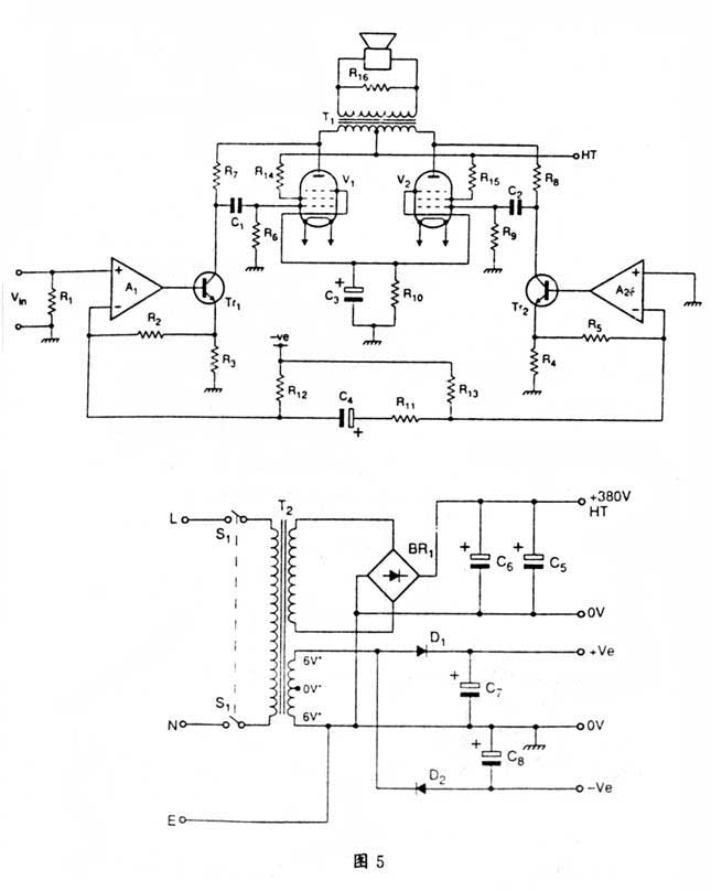
High voltage power supply
The power supply of this circuit is a commonly used general form. The high-voltage secondary of T2 is 280V, which is rectified by BRl full wave, and then smoothed by the parallel combination of C5 and C6. The combination of C5 and C6 suppresses the ripple, and there is a huge energy stored on it-about 68 joules. In this way, even when the load condition is very bad, it also helps to keep the power supply stable.
The power supply to the op amp circuit is taken from the filament secondary of T2. For stereo amplifiers, each channel requires at least 6V, 3A. A 6-0-6V, 50VA transformer is sufficient.
The secondary is connected in series, and D1 and D2 are doubled to provide 2 DC voltages, which are smoothly filtered by C7 and C8. The filament is connected in series to the 12-volt power supply as shown in the circuit diagram. Because this amplifier is completely in balanced working mode, the ripple is effectively suppressed, so the power supply design is simplified.
Make
The production of this design is not complicated, the prototype uses a general chassis and bottom plate. For the wiring of the filament, a 5A speaker cable can be used. The filament wiring should be as close as possible to the bottom plate, but do not double-twist as in the low-level tube circuit.
Fatal high voltages are added to capacitors C5, C6 and all high-voltage lines, and mains power is added to the primary of the power transformer. As soon as the power is turned on, the amplifier composed of EL34 etc. enters the working state, and the filament should be heated before the power is turned off again. As long as the electron tube is connected in the circuit and turned on, the decoupling capacitor will quickly discharge after the power is turned off. If the tube is not inserted into the socket, the high pressure will be maintained for a long time, which may be hours or days.
No adjustment is required for this amplifier. As long as the wiring is correct, this circuit can work normally at the beginning.
in conclusion
Is the effort we made here worth it? Yes, it is worth it. The continuous power given by this prototype is 32W per channel, the full power bandwidth is 5Hz to 55KHz, a 3dB. The distortion measured at 1KHz and 20W output is 0.07%, and the output impedance is only 0.6Ω-far below the standard value of the tube amplifier.
Not only that, this amplifier is also capable of exciting harsh loads and can withstand short circuits at the output without damage.
Component list
Resistance: Unless otherwise stated, all are 1%, 2.5W metal film resistance
R1 56K
R2 ï¼ 5 10K
R3 ï¼ 4 1K8
R6 ï¼ 9 60K
R12 ï¼ 13 68K
R7 ï¼ 8 220K
R10 470K, 3W wire wound
R11 6K8
R14 / 15 470K, lW
R16 1K, 1W
capacitance
Cl, 2 100nF, 1000V WKG polypropylene capacitor
C3 100μF, 100V
C4 220pF, 25V
C5, 6 470μF, 400V
C7, 8 1000μF, 63V
Active device
A1 / A2 TL072
V1 / V2 EL34
Trl, 2 2SC2547E
D1, 2 1N4001
BRl W08
transformer
T1 output transformer 20: 1 turns ratio, center tap. Primary inductance> 8H, leakage inductance <10mH.
T2 power transformer, primary 220V, secondary 280V, 700mA, secondary 6-0-6V, 4A

Follow WeChat

Download Audiophile APP

Follow the audiophile class
related suggestion
Avago Introduces New High Linear Power Amplifier Module Product Avago Technologies ...
The circuit is shown in Figure 1. The chip IC uses the LM1875 of the American NS company, which has a soft tone and low distortion (0.015% ...
The word "Monster" has both positive meaning and ...
When the output power of the digital power amplifier is greater than 50W, it is impossible to use only ...
If an "audiophile" is a group of people who are never satisfied with the sound and "loved the new and the old" with the audio equipment. Then just rely on these so-called "fever spirits" ...
First, the circuit principle and characteristics 1. Power amplifier part (see Figure 1)
There is a well-known saying in the Hi-Fi world that is "briefness first." This means that if ...
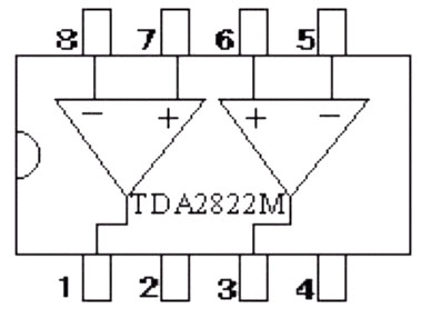
Simple and practical TDA2822M integrated power
TDA2030 is ...

STK465 thick film ...

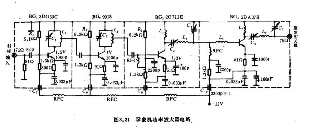
This RF power amplifier can output 2-3 channel signals, covering an area of ​​about one square kilometer, is ...
![[Photo] 15w RF power amplifier](http://i.bosscdn.com/blog/20/06/41/521040781.gif)
![[Photo] Broadband high frequency power amplifier](http://i.bosscdn.com/blog/20/06/41/520536801.jpg)
Low frequency power amplifier
![[Photo] TDA2030 audio power amplifier](http://i.bosscdn.com/blog/20/06/41/5131012891.gif)
Looking at the Hi-Fi amplifiers currently on the market, the output power is 100W ...
![[Photo] Transistor 15W Class A Power Amplifier](http://i.bosscdn.com/blog/20/06/41/513102891.gif)
With the newly launched LM4651 and LM465 from National Semiconductor ...
![[Photo] 125W Class D Subwoofer Power Amplifier](http://i.bosscdn.com/blog/20/06/41/513100868.jpg)
![[Photo] Mark Levinson No. 30 ...](http://i.bosscdn.com/blog/20/06/41/513544752.jpg)
EL34 (6CA7) was first launched by Philips in 1956 ...
![[Photo] 45W transistor tube hybrid power amplifier](http://i.bosscdn.com/blog/20/06/41/513531952.jpg)
The pre-amplifier adopts a European-made TESLA brand low noise high cheek double transistor ...
![[Photo] Gallstone hybrid power amplifier using switching power supply](http://i.bosscdn.com/blog/20/06/41/513524776.gif)
"Simple" means the circuit of the amplifier is simple, making it easier, as long as the picture ...
![[Photo] Simple fool power amplifier](http://i.bosscdn.com/blog/20/06/41/513432946.jpg)
1. Description: & nb ...
![[Photo] LM386 low voltage audio power amplifier ...](http://i.bosscdn.com/blog/20/06/41/513417261.gif)
The Class A transistor power amplifier has a warm and sweet tone, which makes people tempted. But the temperature rise of Class A amplifier ...
![[Photo] Class A power amplifier using SAP15N / P audio pair tube ...](http://i.bosscdn.com/blog/20/06/41/513346769.gif)
The circuit is shown in Figure 5, ...
![[Photo] Using TDA7294 and 2SA1216 / 2S ...](http://i.bosscdn.com/blog/20/06/41/4233420295.gif)
'+ data.data.username +' '; dom + ='
24V, 25.9V, 7S1P
Shenzhen Powercom Electronics Co., Ltd. , https://www.expowercome.com