As an important part of the automatic fire alarm system, the fire floor display is a digital fire alarm display device installed on the floor or in an independent fire zone. It is connected to the fire alarm controller through the alarm bus, and processes and displays the data on the alarm bus. The built-in single chip microcomputer in the fire floor display will judge, analyze and process the received bus information, convert the alarm detector address number into the corresponding fire alarm location information (such as room number and room type, etc.), and pass the LCD together with the fire alarm type It is displayed and an audible and visual alarm signal is issued to notify personnel in the fire area.
At present, most existing fire floor displays in China use 51 single chip microcomputer as MCU. Due to the limitation of the ROM addressing space, most fire floor displays can only display the floor number and address number of the fire alarm, and can not prompt the specific fire alarm location with different situations in intuitive Chinese characters. If the Chinese character information is distributed to the display of each floor through the bus, the huge traffic will bring a heavy load to the fire alarm system bus, resulting in inefficiency of the entire fire alarm system and delaying the timing of fire alarm reporting. This paper proposes a large-capacity Chinese character fire floor display based on CAN bus, which solves the above problems well.
2 Overall function description of the fire alarm system
In the fire alarm control system, the central fire alarm controller communicates with each unit in real time through the CAN bus and completes various control and alarm functions. The unit is the general term for fire detectors, manual alarm buttons, input / output modules, floor displays and other equipment. They are system terminals that directly detect fire signals and report them to the controller through the channel, and at the same time receive the linkage information (starting the fire extinguishing device controlled by the input and output module) from the various channels to the unit, and display information (floor display shows fire Information) etc. The channel is a general term for devices such as loop modules, adapter modules and bus control panels. They are the channels of the control equipment and the terminal, and are the relay equipment composed of the topology network. The overall structure of the fire alarm control system and the position of the floor display in the system are shown in Figure 1.

Figure 1 Fire alarm control system structure and location display of floor display
3 System functions and hardware description
3.1 Design Scheme of Chinese Character Floor Display Hardware
As shown in Figure 2, the Chinese character floor display includes a microcontroller and its peripheral circuits, CAN bus module, FLASH memory, Chinese character liquid crystal module, UART interface, as well as lights and keys, buzzer. The single chip microcomputer can receive the Chinese character information uploaded by the PC through the UART and store it in the FLASH as a query database for address information. The CAN bus communication is carried out through the CAN communication module composed of the CAN controller MCP2510 and the CAN bus driver PCA82C250 and the fire alarm controller. If there is a fire alarm, the single chip microcomputer will record the fire alarm information, query FLASH to get the Chinese character address information of the fire alarm, and scroll the fire alarm and information query results on the Chinese character LCD. At the same time, when a fire alarm occurs, you can also quickly query the fire alarm information through the query key, alarm through the buzzer, mute the sound through the mute key, and light the LED alarm. When there is no fire alarm, you can check whether each function can work normally through the self-check key.

Figure 2 Block diagram of Chinese character floor display
3.2 FLASH memory circuit design
SST29SF040 selected by FLASH is a high-speed programmable flash memory launched by SST. It conforms to the JEDEC standard and has a storage structure of 512K × 8 Bits; the chip erasing and writing time is fast, the entire chip erasing takes only 70 milliseconds, the segment erasing requires only 18 milliseconds, and the word programming writing time is only 14 micro Seconds; high reliability, able to repeat writing 100,000 times, data can be saved for 100 years without loss.
The capacity of SST29SF040 is 512K Bytes, and the ROM direct addressing range of 51 series single-chip is 64K Bytes. If it is used directly without processing, a lot of storage space will be wasted. We used a paging storage method to make full use of the FLASH storage space, greatly expanding the MCU ROM addressing range. According to the calculation of 32 Bytes per piece of Chinese character information, in theory, a maximum of 16,384 pieces of fire address information can be stored, which is enough to cope with most complex engineering environments. Figure 3 shows the memory circuit. The most significant address lines A16-A18 are connected to P1.0-P1.2 of the microcontroller, so the FLASH memory implements an 8-page, 64K external storage structure. When reading and writing FLASH each time, assign different values ​​to P1.0-P1.2 to achieve different page selections. Assuming that page is the variable of the page number to be selected (0-7), the page selection operation before reading and writing can be realized in Keil Cx51 with the following statement: P1 = (P1 & 0xf8) | page;

Figure 3 FLASH memory paging storage circuit
3.3 Design of Chinese character LCD display module
We chose the OJM2 * 8A Chinese character LCD module of Jinpeng Electronics Company as the display device. OJM2 * 8A Chinese LCD display module contains GB 2312 15 * 15 dot matrix national standard first and second grade simplified Chinese characters and 8 * 8 dot matrix and 8 * 16 dot matrix ASCII characters, users can enter GB2312 area code or ASCII code to achieve Text display. The area code of each Chinese character only occupies two bytes, which is 1/16 of the storage unit required by the original Chinese character dot matrix.
The interface protocol of Chinese character LCD module is request / response (REQ / BUSY) handshake. Answering BUSY high level (BUSY = 1) indicates that the LCD module is busy with internal processing and cannot receive user commands; BUSY low level (BUSY = 0) indicates that the LCD module is idle and waiting to receive user commands. Sending commands to the LCD module can start at any time after BUSY = 0, first put the current byte of the user command on the data line, then send a high-level REQ signal (REQ = 1) to notify the LCD module to process the current data line Command or data. The LCD module reads the command or data on the data line immediately after receiving the external REQ high-level signal, and at the same time changes the response line BUSY to high level, indicating that the module has received the data and is busy with the internal processing of this data. At this point, the user's write operation to the module has been completed. The user can cancel the signal on the data line and perform other tasks than the module display, and can continuously query whether the answer line BUSY is low (BUSY = 0?). If BUSY = 0, indicating that the module's write operation to the user has been completed, and the next data can be sent. If a complete command for displaying Chinese characters is sent to the module, a total of 5 bytes including coordinates and Chinese character codes are required. The module starts to execute the internal operation of the whole command after receiving the last byte, so the last byte response BUSY high level (BUSY = 1) lasts longer. The timing diagram of writing Chinese characters to the LCD module is shown in Figure 4.
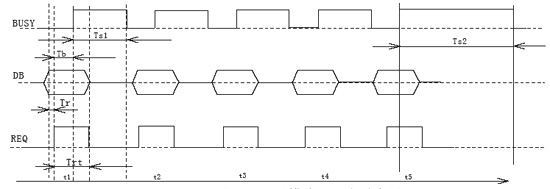
Figure 4 Timing diagram of writing Chinese characters to the LCD module
3.4 CAN bus communication module design
We chose the MCP2510CAN controller from Microchip and the PCA82C250CAN transceiver from Philips to build the CAN bus communication module. MCP2510 supports CAN2.0A / B protocol, can receive and send standard frames, extended frames and remote frames under 2.0 protocol. The MCP2510 has three transmit buffers and two receive buffers, which can perform receive filtering and message management to prevent excessive transmission and excessive reception from forming congestion. Its biggest advantage is that it has an SPI port with a transmission rate of up to 5Mb / S, saving MCU ports and improving communication speed. The 82C250CAN bus transceiver of Philips can be seamlessly connected with the MPC2510. It has high-speed mode, slope control mode and delay mode. After many experiments, it was confirmed that its work is the most stable in the slope control mode, and the speed can also meet the transmission rate of 10Kbps of the system.
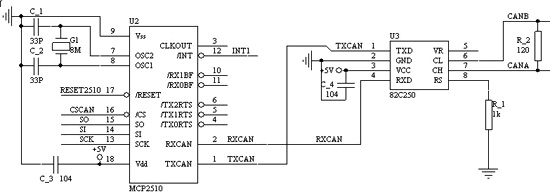
Figure 5 CAN bus communication circuit
The CAN bus communication module circuit is shown in Figure 5. The single chip is directly connected to the SPI port of the MCP2510 through the I / O port, and the SPI interface protocol is realized by software simulation. PCA82C250 serves as the interface between MCP2510 and the physical CAN bus. If you need to further improve the anti-interference ability of the system, you can add a photoelectric isolator between MCP2510 and PCA82C250.
4 System software design
The function of the Chinese character floor display software is mainly 1. Write the Chinese character information file sent from the serial port to FLASH storage. 2. Carry out CAN communication with the fire alarm controller. If there is any fire alarm information, look up the Chinese character address information in FLASH and display it on the Chinese character LCD. If there are multiple fire alarm information, scroll through the various information.
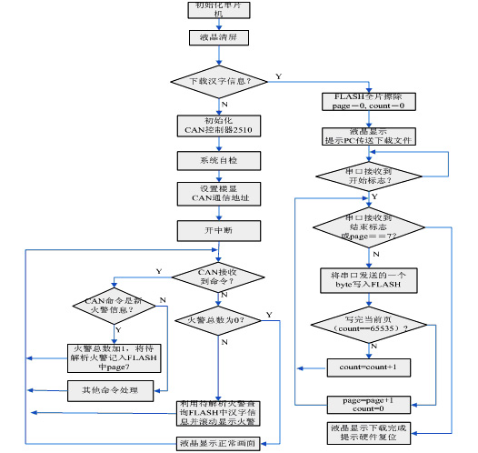
Figure 6 Flow chart of Chinese character floor display software
Figure 6 is a flow chart of the Chinese character floor display software. Use page (value 0-7) to represent the read and write FLASH page, and count (value 0-65535) to represent the address within each page. Among them page0-page6 is used to store the Chinese character information downloaded through the serial port, and page7 is used to store the received fire alarm and other dynamic information. Once a new fire alarm is received, the corresponding Chinese character information in FLASH is queried and scrolled on the LCD.
In order to quickly locate the fire alarm Chinese character address information, we use an array structure to store. Although this will cause some empty addresses in the storage due to the unequal length of the actual fire alarm address, the storage efficiency is not high, but because our search for the array is a fast search that can be directly located, there is no need to use complex data such as linked lists The structure also avoids complex search algorithms such as binary search. For the single-chip microcomputer, it is actually worth the relatively high time efficiency at the cost of a relatively small space.
5 Conclusion
The large-capacity Chinese character fire floor display based on CAN bus proposed in this paper solves the defects of the existing fire floor display better. For the data storage requirements of the ROM 64K addressing space larger than 51 single chip microcomputer, the access method of paging storage can solve this problem well. By storing large-capacity data information in FLASH, it can avoid that the fire alarm cannot be communicated in time due to excessive communication data flow on the CAN bus, and the alarm timing is delayed. Moreover, the Chinese character information in FLASH can be erased and written online through the serial port, which is convenient for on-site debugging. At present, the product has been put into practical use, and the user response is running well.
references
[1] Zhu Ming, Wang Shu. Design and implementation of a subordinate network of a large-scale fire alarm system based on CAN bus. Fire protection technology and product information, 2003, (12): 5 ~ 8
[2] Wang Lifeng, Wang Xiaoping, Geng Qingbo, Peng Xiwei. Design of guest room communication controller based on CAN bus. Microcomputer Information, 2005, (16): 3 ~ 7
[3] Xu Aijun, edited by Peng Xiuhua. Keil Cx51 V7.0 MCU high-level language programming and uVision2 application practice. Electronics Industry Press, 2004
High Frequency AC Power Supply
Adapter Power Regulated,Ac To Dc Regulated Power Supply,High Voltage Regulated Power Supply,High Voltage High Frequency Power Supply
Yangzhou IdealTek Electronics Co., Ltd. , https://www.idealtekpower.com