In addition, with the advancement of integrated circuit manufacturing technology and the development of power electronics technology, AC servo has also made great progress. The emergence of intelligent power modules, advanced power electronic devices that integrate three-phase inverters and protection circuits, isolation circuits, energy consumption braking circuits, etc., make AC servo control more convenient, lower power consumption, and more switching time Short, wider frequency conversion range, more superior performance. All these make the AC servo have obvious advantages over DC servo.
1 System Overview
The hardware of the AC servo digital system uses DSP as the signal processor, the rotary encoder and the current sensor to provide the feedback signal, and the intelligent power module IPM as the inverter. The signal from the sensor is processed by filtering and shaping and then fed back to the DSP for calculation. DSP processes the reference signal and feedback signal to adjust the current loop, speed loop, and position loop of the servo system. Finally, the PWM signal is output to drive the IPM module to realize the servo closed-loop control of the motor. The hardware structure of the system is shown in Figure 1.
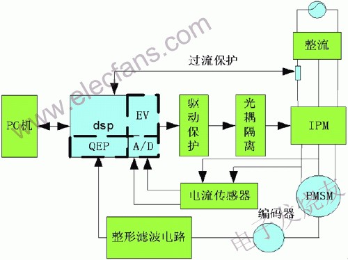
Figure 1 hardware structure diagram
The control of the system is the three-loop control mode, the position control is the outer loop and the final goal, the speed control is the middle loop, and the current control is the inner loop. In order to ensure that the dynamic response speed and positioning do not produce oscillation, the current loop and speed loop are both PID adjusted, and the position regulator is adjusted by PI. The control block diagram of the system is shown in Figure 2:
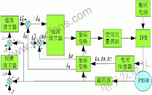
Figure 2 Control system block diagram
The actual position signal of the rotor detected by the encoder is compared with the given position signal of the system, and the compared difference is adjusted by the position regulator PI to output the given signal of the rotor speed. The given speed signal is then compared with the actual speed signal detected by the encoder For comparison, after the speed difference is adjusted by the speed regulator, the given current command value is output, which is PWM control after the current feedback actual value is compared.
2 Vector control
In synchronous motors, the spatial angle between the excitation magnetic field and the armature magnetomotive force is not fixed, so the electromagnetic torque cannot be directly controlled by adjusting the armature current. Through the external control system of the motor, the armature magnetomotive force is spatially oriented relative to the excitation magnetic field, and the angle between the two is controlled to maintain a fixed value, and the amplitude of the armature current is also controlled. This control method is called For vector control.
Vector control is equivalent to controlling the three-phase current of the armature by controlling the current of the two-phase rotor reference coordinate dq axis. This equivalent can be clearly understood through the previous system control block diagram, which can be expressed by the following formula:
 (1)
(1)
The encoder installed at the non-load shaft end of the motor detects the rotor pole position at any time, continuously obtains the position angle information, and knows θ by detecting in real time, that is to say, it can carry out real-time coordinate changes, and the converted current carries out the inverter Control, generate PWM waveform to control the motor.
3 Position and speed detection
The AC servo motor is equipped with an encoder for position and speed measurement. In most cases, the signal waveform directly from the encoder is irregular and cannot be directly used for control, signal processing and long-distance transmission, so the signal must be shaped After filtering and filtering, it becomes a rectangular wave and then feeds it back to the DSP. After processing, the two orthogonal encoder signals A and B are directly sent to the QEP pin of the DSP after voltage conversion, and the steering signal and 4 times are generated by the decoding logic unit. Frequency pulse signal. The turn signal is determined based on the phase lead and lag of the two signals. Due to the problem of forward and reverse rotation, the counter is required to be reversible, so the general timer 2 is set to the directional up and down counting mode, and the quadrature-encoded pulse after frequency multiplication is used as the input clock of timer 2 to count, the direction of the count Determined by the turn signal, if the input phase of QEP1 leads, the count is increased, otherwise the count is decreased. The position and speed can be determined by the pulse number and pulse frequency. The total number of pulses per revolution is denoted by M, and the number of pulses at time T1 is m1, then the angle of rotation of the motor can be calculated according to the following formula.
![]() (2)
(2)
In the case of multiple rotations, together with the count value of the Z-phase zero pulse of the encoder and the clearing of the corresponding timer 2, you can know how many revolutions and angles the motor shaft has turned. The calculation of the motor rotor speed can be based on the MT speed measurement method to determine the speed formula of the encoder as follows:
![]() (3)
(3)
M1—Number of encoder pulses recorded by the counter within a fixed time;
M2—Number of DSP clock pulses recorded in a fixed time;
N—the number of encoder lines, that is, the number of encoder pulses before frequency multiplication;
Fclk—DSP clock frequency.
4 Conclusion
In summary, the digital AC servo drive studied in this paper has a modular design, simple hardware structure, and easy software programming. Can easily realize the communication between PC or PLC and the controller, so that the host computer can accept the real-time parameters of the control system and transfer the parameters to the servo control system to directly control the servo system.
ZH Power is a leading global supplier of power supplies with all global AC input voltages range from 100VAC to 240VAC single phase. This wall plug class 2 power supplies is one wall mount style, high efficiency and reliability class II installations AC to DC Power Adapter and support class 2, Limited Power Source (LPS) requirements. The series plug in Power Supply offers products output ranging from 4.2 Watts to over 40 Watts, covers a wide variety of AC input blades including America blade, Europe blade, Korea blade, Australia blade, United Kingdom blade and China blade.
Wall Plug UL Class 2 Power Supply
Wall Mount Adapter,Power Supply,Dc24V Power Supply,Ac Power Supply,Class 2 Power Supply 24v,Class 2 Power Supply 12v
Shenzhenshi Zhenhuan Electronic Co Ltd , https://www.szzhpower.com