DS3881, DS3882, DS3984, DS3988, DS3991, DS3992 and DS3994 are CCFL (Cold Cathode Fluorescent Lamp) controllers, which provide backlight for LCD (Liquid Crystal Display). Each controller has 2 input pins LCM and OVD, used for fluorescent lamp monitoring and current regulation. There are 4 thresholds for these 2 inputs. This article introduces the definition of these thresholds and how to determine the correct threshold according to the specific application.
The LCM and OVD thresholds and their corresponding benchmarks DS3881, DS3882, DS3984, DS3988, DS3991, DS3992, and DS3994 CCFL (Cold Cathode Fluorescent Lamp) controllers each have two inputs: LCM for lamp current monitoring, OVD For overvoltage detection. There are 4 thresholds corresponding to LCM and OVD. Table 1 lists the descriptions and symbols for each threshold.
Table 1. Threshold description and symbols
Both the LCM and OVD pins have an internal DC bias VDCB. For DS3881 and DS3882, the bias is 1.1V; for DS3984, DS3988, DS3991, DS3992, and DS3994, the bias is 1.35V. The threshold can be referenced to VDCB or signal ground (GND).
Depending on the voltage reference used, the thresholds specified in the data sheet seem to be different, although they are essentially the same. In the data sheets of DS3881, DS3882, DS3984 and DS3988, these four thresholds are referenced to VDCB. In the data sheets of DS3991, DS3992, and DS3994, these four thresholds are referenced to ground, so they include VDCB. For example, the DS3984 lamp adjustment threshold (typical value) given in the data sheet is 1.0V relative to VDCB and 1.35V relative to VDCB. In the data of DS3994, the same parameter value is 2.35V, and the value is based on the signal ground. Therefore, the DS3984 and DS3994 lamp adjustment thresholds are actually the same. Note 3 of these two data sheets explains this.
Determine the correct threshold according to the application. Because the threshold will vary with the reference used, the user needs to determine the correct reference (VDCB or ground) to select the correct external compensation value. If the LCM and OVD signals are AC-coupled, they are usually referenced to VDCB, which is suitable for applications where each channel drives a single lamp. However, if AC coupling is not used, the threshold should be referenced to ground. This rule is generally applicable to applications where multiple lamps are driven per channel. The following two examples explain this principle.
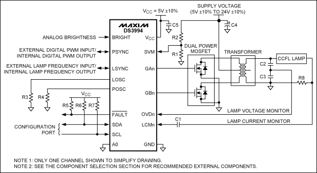
Each channel drives a lamp. In such applications, the internal DC bias on the LCM and OVD pins allows AC-coupled inputs. This design will make the external circuit very simple. Figure 1 shows a typical working circuit for this type of application.

Figure 1. Typical operating circuit for driving one lamp per channel
In this application, the threshold is referenced to VDCB. Table 2 lists the threshold values, which may be different for other components.
Table 2. DS3994 LCM and OVD thresholds (Figure 1)
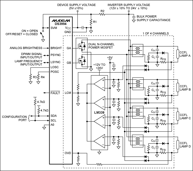
Multiple lamps per channel Figure 2 shows a typical working circuit for driving multiple lamps per channel of the DS3994. In this type of application, the lamp current and voltage must be "wired-OR" logic and fed to the DS3994's LCM and OVD inputs. Some external circuits are used in the circuit, including voltage divider and peak detector. Unlike the application of driving one lamp per channel, the application of driving multiple lamps per channel does not use AC coupling capacitors at the LCM input. The DS3994 controls the lamp current based on the peak signal measured at the LCM input. In the absence of AC coupling capacitors, the peak control level is DC bias (1.35V) plus the lamp adjustment threshold (1.0V), which is 2.35V (nominal). Therefore, at the LCM input, the peak voltage generated by the lamp's current feedback resistor must decay to the target value of 2.35Vpeak, so that the device can control the lamp current to a suitable level. Similarly, the OVD threshold for this application is 2.35V to ground.

Figure 2. Typical operating circuit for driving multiple lamps per channel
Refer to Table 3 for the thresholds used in Figure 2. The voltage is referenced to ground. For other components, these values ​​may be different.
Table 3. LCM and OVD thresholds of DS3994 (Figure 2)
Summary Each channel of the DS3xxx CCFL controller has 4 thresholds for lamp monitoring and adjustment. Depending on the benchmark used, the thresholds given in the corresponding data may be different. When the LCM and OVD signals are AC coupled, the threshold is usually based on DC bias (VDCB). This method is generally applicable to the application of one lamp per channel. When the LCM and OVD signals are not connected to the corresponding pins through AC coupling capacitors, the threshold value is referenced to ground. This design is generally suitable for applications where multiple lamps are driven per channel.
The LCM and OVD thresholds and their corresponding benchmarks DS3881, DS3882, DS3984, DS3988, DS3991, DS3992, and DS3994 CCFL (Cold Cathode Fluorescent Lamp) controllers each have two inputs: LCM for lamp current monitoring, OVD For overvoltage detection. There are 4 thresholds corresponding to LCM and OVD. Table 1 lists the descriptions and symbols for each threshold.
Table 1. Threshold description and symbols
| Associated Pin | Symbol | DescripTIon |
| LCM | VLOT | Lamp off threshold |
| VLOC | Lamp overcurrent threshold | |
| VLRT | Lamp regulaTIon threshold | |
| OVD | VOVDT | Lamp overvoltage threshold |
Both the LCM and OVD pins have an internal DC bias VDCB. For DS3881 and DS3882, the bias is 1.1V; for DS3984, DS3988, DS3991, DS3992, and DS3994, the bias is 1.35V. The threshold can be referenced to VDCB or signal ground (GND).
Depending on the voltage reference used, the thresholds specified in the data sheet seem to be different, although they are essentially the same. In the data sheets of DS3881, DS3882, DS3984 and DS3988, these four thresholds are referenced to VDCB. In the data sheets of DS3991, DS3992, and DS3994, these four thresholds are referenced to ground, so they include VDCB. For example, the DS3984 lamp adjustment threshold (typical value) given in the data sheet is 1.0V relative to VDCB and 1.35V relative to VDCB. In the data of DS3994, the same parameter value is 2.35V, and the value is based on the signal ground. Therefore, the DS3984 and DS3994 lamp adjustment thresholds are actually the same. Note 3 of these two data sheets explains this.
Determine the correct threshold according to the application. Because the threshold will vary with the reference used, the user needs to determine the correct reference (VDCB or ground) to select the correct external compensation value. If the LCM and OVD signals are AC-coupled, they are usually referenced to VDCB, which is suitable for applications where each channel drives a single lamp. However, if AC coupling is not used, the threshold should be referenced to ground. This rule is generally applicable to applications where multiple lamps are driven per channel. The following two examples explain this principle.
Each channel drives a lamp. In such applications, the internal DC bias on the LCM and OVD pins allows AC-coupled inputs. This design will make the external circuit very simple. Figure 1 shows a typical working circuit for this type of application.

Figure 1. Typical operating circuit for driving one lamp per channel
In this application, the threshold is referenced to VDCB. Table 2 lists the threshold values, which may be different for other components.
Table 2. DS3994 LCM and OVD thresholds (Figure 1)
| Parameter | Symbol | Min | Typ | Max | Units |
| Lamp off threshold | VLOT | 0.30 | 0.40 | 0.50 | V |
| Lamp overcurrent threshold | VLOC | 1.80 | 2.00 | 2.20 | V |
| Lamp regulaTIon threshold | VLRT | 0.94 | 1.00 | 1.06 | V |
| OVD threshold | VOVDT | 0.90 | 1.00 | 1.10 | V |
Multiple lamps per channel Figure 2 shows a typical working circuit for driving multiple lamps per channel of the DS3994. In this type of application, the lamp current and voltage must be "wired-OR" logic and fed to the DS3994's LCM and OVD inputs. Some external circuits are used in the circuit, including voltage divider and peak detector. Unlike the application of driving one lamp per channel, the application of driving multiple lamps per channel does not use AC coupling capacitors at the LCM input. The DS3994 controls the lamp current based on the peak signal measured at the LCM input. In the absence of AC coupling capacitors, the peak control level is DC bias (1.35V) plus the lamp adjustment threshold (1.0V), which is 2.35V (nominal). Therefore, at the LCM input, the peak voltage generated by the lamp's current feedback resistor must decay to the target value of 2.35Vpeak, so that the device can control the lamp current to a suitable level. Similarly, the OVD threshold for this application is 2.35V to ground.

Figure 2. Typical operating circuit for driving multiple lamps per channel
Refer to Table 3 for the thresholds used in Figure 2. The voltage is referenced to ground. For other components, these values ​​may be different.
Table 3. LCM and OVD thresholds of DS3994 (Figure 2)
| Parameter | Symbol | Min | Typ | Max | Units |
| Lamp off threshold | VLOT | 1.65 | 1.75 | 1.85 | V |
| Lamp overcurrent threshold | VLOC | 3.15 | 3.35 | 3.55 | V |
| Lamp regulaTIon threshold | VLRT | 2.29 | 2.35 | 2.41 | V |
| OVD threshold | VOVDT | 2.25 | 2.35 | 2.45 | V |
Summary Each channel of the DS3xxx CCFL controller has 4 thresholds for lamp monitoring and adjustment. Depending on the benchmark used, the thresholds given in the corresponding data may be different. When the LCM and OVD signals are AC coupled, the threshold is usually based on DC bias (VDCB). This method is generally applicable to the application of one lamp per channel. When the LCM and OVD signals are not connected to the corresponding pins through AC coupling capacitors, the threshold value is referenced to ground. This design is generally suitable for applications where multiple lamps are driven per channel.
Radio modems are dedicated to transfer data between two or more locations. GrandComm`s radio modems operate in VHF and UHF frequency band and can cover a distance of over 50 kilometers. The radio modems can provide programmable serial baud rates from 1200bps to 115200bps.
GrandComm`s radio modem products are designed to industrial standards and well-suited for SCADA, telemetry and process control applications in wireless environment. The radio modem can communicate data of remote control signals, telemetry signals from a transducer, computer`s RS232 port, GPS position signals, or a digital terminals.
Radio Modem
Radio Modem,RF Modem,Data Radio Modem,Serial Radio Modem
Shenzhen PuFang Technology Co., Ltd. , https://www.hytelus.com