The power amplifier is an indispensable key component of the millimeter wave band transmitter. The output power determines the range and anti-interference ability of the entire system. In the millimeter wave system, as the frequency increases, the output power of a single MMIC chip can no longer meet the actual use requirements, especially the non-atmospheric window frequency band, because the transmission of electromagnetic waves in this frequency band is seriously attenuated by the absorption of oxygen molecules and water vapor molecules . Generally used in military security work and short-range radar detection and communication systems, the output power of the corresponding device is also small. Therefore, the power synthesis method is often used to combine multiple amplifier units to achieve a larger power output.
The amplifier works in the V band and is used for a close-up detection system. It fully utilizes the attenuation characteristics of the non-atmospheric window band to achieve confidentiality and anti-interference.
1 Design of power amplifier
1.1 Technical index requirements
According to the basic requirements of the system, the main technical indicators of the amplifier: operating bandwidth 2 GHz; output power ≥200 mW; gain 20 ~ 25 dBm; input and output port WR15.
1.2 Selection of power devices
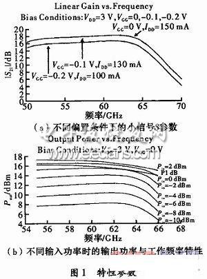
In order to meet the requirements of technical indicators, a three-terminal FET power amplifier device with a wide operating frequency band is selected. The FMM5715X of Eudyna Devices was selected as the power synthesis unit. The FMM5715X is a multi-tube synthesized power monolithic matched to 50 Ω within the port impedance. Operating frequency is 57 ~ 64 GHz; operating temperature range: -45 ~ + 85 ℃, storage temperature range -55 ~ + 125 ℃; maximum allowable input power 3 dBm; can work with single power supply, bias 3 V / 150 mA at DC Under the conditions, the typical performance P1 dB at 60 GHz is 16 dBm, the saturation power is 17 dBm, and the small signal gain is 17 dB. The characteristic parameters are shown in Figure 1.
1.3 Synthetic network design
1.3.1 Overall scheme of synthetic network
In the V band, the output power of a single tube is far from the power output demand. Even if it is a MMIC power device using multiple tube synthesis, the single device cannot meet the technical specifications. Therefore, the use of multi-device power synthesis technology is an inevitable choice for the completion of this project. At present, the more mature power synthesis technology is to use a two-way bridge with a better port standing wave, and realize multi-way synthesis by multi-stage cascade. The designed amplifier adopts two-way binary multi-level power synthesis technology based on the waveguide low-loss transmission line structure. The synthesis network consists of two parts, a power driving stage and a power amplification synthesis stage, each part includes a 3-stage binary network, which is composed of waveguide branch lines. Bridge and waveguide-microstrip transition. The synthetic network block diagram is shown in Figure 2.

For 8-way power distribution, the network loss of each stage is counted as 0.3 dB, and the path loss is calculated as 0.5 dB. To saturate all power devices during synthesis, the input power of FMM5715X should be> 2 dBm. The power at the input of the power distribution network is 12.4 dBm. Obviously, the single-channel FMM5715X driver stage is sufficient to meet this requirement.
When all power devices in the synthesis network are in the saturated working state, the single-stage loss is 0.3 dB, the three-stage power synthesis, the synthesis efficiency caused by the loss is 80%; if the maximum amplitude and phase imbalance between the synthesis branches are considered 3 dB and 30 ° respectively, resulting in a corresponding synthesis efficiency of 90%; for 8-way power synthesis, the total synthesis efficiency is
When the device works in saturation, the 8-channel composite output is 17 + 7.07 = 24.07 dBm or 255 mW, which meets the requirements of the technical indicators. The loss of each part of the circuit is 4 8 dB, and the small signal gain of the entire synthesis amplifier is about 29.2 dB.
Single solar cells cannot be used directly by the power source. The power supply must have a number of single battery, parallel connection and tightly encapsulated components. Solar panels (also known as solar cell components) are central to solar power systems and are the most important part of solar power systems.At present, the crystalline silicon materials (including polycrystalline and monocrystalline silicon) is the main photovoltaic material, its market share of over 90%, and in the future a long time also is still the mainstream of solar cell materials.
Mono 350W Solar Panel,350W Solar Panel,Solar Panel Distributor
Yangzhou Bright Solar Solutions Co., Ltd. , https://www.cnbrightsolar.com