As the automotive industry continues to pursue the goals of safety, reliability, extreme performance, comfort and low cost, the high complexity of the system network in the car makes the wiring harness too large, resulting in increased costs and difficult to continuously improve the network architecture, which conflicts with the former.
This article refers to the address: http://
So Germany's Bosch proposed the CAN BUS (Controller Area Network) in 1985, which not only solved the problem of continuous increase of the wiring harness inside the car, but also laid the foundation for a reliable and efficient network system in the future. In 1993, CAN BUS was standardized (ISO-11898). Due to its high reliability and error detection capabilities, CAN BUS is also widely used in ships, avionics, mass transit, agricultural equipment, medical equipment, and industrial control.
CAN BUS architecture and features
CAN BUS is a technical specification of serial two-wire differential transmission (see Figure 1). The MCU is responsible for computing data. The CAN Controller processes the processed data and transmits "0" or "1" data. The CAN Transceiver is converted by CAN Transceiver. CAN High and CAN Low generate differential signals (see Figure 2). Among them, CAN High voltage minus CAN Low voltage less than 0.5V means logic state is "1", and CAN High voltage minus CAN Low voltage greater than 0.9V means logic state is "0", so the transmission bit string in Figure 2 is 101. Noise can be avoided by differential means, and the termination resistance of 120Ω is to prevent interference caused by reflection after information transmission.
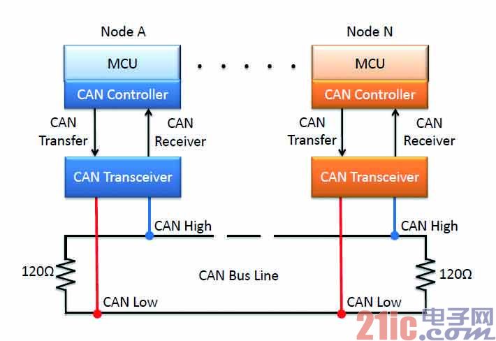
Figure 1 CAN BUS application architecture
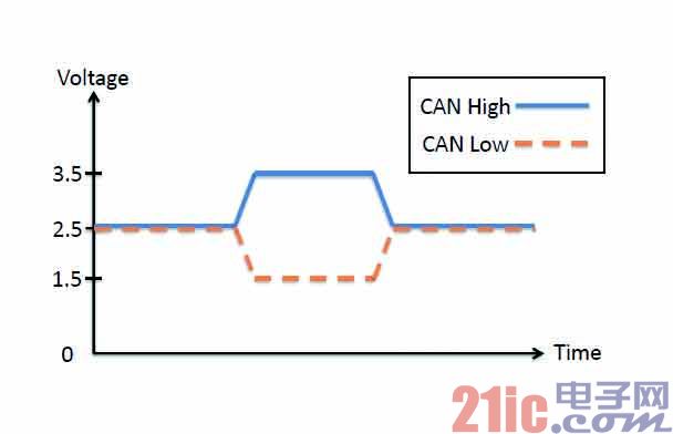
Figure 2 CAN BUS output level
The minimum unit on the CAN BUS is a node. Each node can actively send information to the bus, and can also request specific nodes to return information. It is not limited to only one master. Each message (Message) starts with the identification subfield (ID Field) and determines the priority of the transmitted information by the identification value. The smaller the value, the higher the priority. So the transfer of information is not defined on the node, but on the information. Because it is a tandem architecture plus a recognition mechanism (ID), the hardware and software can easily add or remove nodes without modification, which not only reduces the wiring cost but also reduces the maintenance complexity. The console architecture achieves a more complete intelligent network device.
Information transfer can be made through the settings on the node, so that information can be received into the buffer by each node, or you can choose to ignore the information. The CAN BUS also supports remote data request. When the information identification value conforms to the internal identification value of the node, and the information is a remote message, the designated node will transmit the corresponding data. Users can use this feature to communicate between nodes and nodes.
On the CAN BUS, the transmission speed can be as fast as 1 Mbps. The user can modify the transmission speed by modifying the bit timing setting, and the transmission distance decreases as the communication speed increases. For example, when the communication speed is 40 Kbps, the communication distance can reach 1 km. When the communication speed is 1Mbps, the communication distance can be up to 40m, and the user can make the deployment according to the application.
Trustworthy helper
Strong fault tolerance
The CAN BUS protocol has a fairly reliable error handling and error detection mechanism. These are hardware automatic detection reactions. Under this mechanism, the transmission of network information is not only efficient but also more convenient to use.
Automatic retransmission
When a node on the bus detects an error, the hardware automatically resends the message to the bus until the node responds with an ACK (Acknowledged) to stop the message.
Error detection
CAN BUS provides five error detection mechanisms, namely Bit Error, Stuff Error, CRC Error, Form Error, and Ack. Error), using these error detection mechanisms to make the transmission on the bus more stable without user intervention.
Error notification
When an error is detected, the node sends an Error Message to the bus, so that all nodes on the bus know that an error has occurred at this time in order to make a relative response, including retransmission or stop transmission.
Error recovery and elimination
In the CAN protocol, each node is standardized to have a Transmit Error Counter (TEC: Transmit Error Counter) and a Receive Error Counter (REC: Receive Error Counter). The status of the current node is determined according to the values ​​of the TEC and the REC. Once the TEC is greater than 255, the hardware will take the node offline and temporarily not receive and send signals to the bus. When a specific situation occurs, the user can re-initialize the node and restart monitoring the signal on the bus. In order to avoid serious errors in the bus caused by the individual nodes, the transmission of other nodes is affected.
Unlimited possible application system
CAN BUS application examples
Elevator system
The traditional elevator system adopts relay logic circuit, which has problems such as excessive wiring harness and inconvenient maintenance. It is changed to CAN to construct the system, which not only greatly reduces the wiring harness, but also increases the system reliability, and has the advantages of simple construction and convenient system debugging.
Bridge strain gauge (Strain Gage)
In view of the frequent transmission of natural disasters, bridge bridges are used to monitor the health of bridges to avoid casualties. However, most of the traditional strain gauges are placed on the bridge and require personnel to be present and cannot be remotely monitored. By using the long transmission distance of CAN BUS at low speed, strain gauges can be placed on the bridges in the planned area, and connected to the CAN BUS to return the monitoring center to monitor the bridge situation, greatly reducing labor costs.
Vehicle monitoring system (Recorder with car information)
Because of the frequent accidents in the car accident, the use of the driving recorder to grasp the road ahead, as a function of the car accident. However, the monitor can only take the image of the road ahead, but can not effectively control the information inside the vehicle, such as the current speed, throttle status and so on. Using CAN to process driving information, and then transmitting it to the video monitor via a high-speed interface such as SPI (Serial Peripheral Interface) or I2C (Inter-Integrated Circuit), it is possible to add the current in-vehicle information to each video recording, making it more advantageous for the car accident. evidence of.
Vehicle Diagnostic System (OBDII)
OBDII (On Board Diagnosis - II) is an agreement that generates a fault warning signal when the vehicle fails, reminding the driver to enter the factory for maintenance. We can use the CAN-supported MCU to build a diagnostic system using USB (Universal Serial Bus) device and CAN. The OBDII connector can be connected to the car bus at any time, and the received message can be transmitted to the computer via USB. The program is used to diagnose the abnormal signal inside the car, thus speeding up the maintenance of the car.
Easy to use
CAN BUS demonstration system
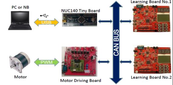
Figure 3 CAN BUS application motor control system
Because of its high scalability, high reliability, real-time performance and low cost, CAN BUS not only becomes the core of the development technology of automotive network systems, but also exerts powerful and significant technical capabilities in other industries. In order to better understand the overall operation of CAN BUS, a commonly used M0 MCU is used here to demonstrate a motor control system that transmits control commands and status messages via CAN BUS (Figure 3), where NUC140 Tiny Board, Learning Board No.1/ No/2 and Motor Driving Board are different nodes on the CAN bus, respectively, using the computer USB to connect to the NUC140 Tiny Board, and decoding the message into CAN through the NUC140 microprocessor to realize the link between the computer and the CAN BUS, and each node Can send and receive system operating status and control commands. Therefore, in the demonstration system, each node can receive the real-time status message of the motor through the link of the CAN BUS and the conversion of the NUC140 microprocessor, and display the LCD screen on the board or the human-machine interface on the computer.
Shenzhen Isource lighting Co., Ltd , https://www.isourceled.com