Why does the loop current go to the zero line without going to the ground line, and the leakage current goes to the ground line without going to the zero line . What is the principle of the zero line ground line ?
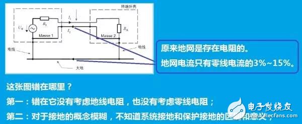
 As shown in the figure, the principle of the ground and neutral lines has been unclear. What are the two ends of the ground line , and what are the two ends of the neutral line . Why does the leakage current go to the ground and the current of the return line does not go to the ground. Get fainted
The pictures are all marked by myself and may have errors.
one
The problem of the subject is quite good. Fortunately, there are two things: first, the title is good, and the topic is directly cut into the theme. Second, the understanding of the protection of the neutral line is well-placed, and it is indeed a cognitive blind spot for many people. The exact name of the neutral line is the protection neutral.
First of all, the answer: the subject of the subject itself is wrong. It should be noted that the protection neutral line is the merged line between the neutral line and the ground line, and the protection neutral line includes the ground line function.
Now, let me answer the question.
Let us see Figure 1:
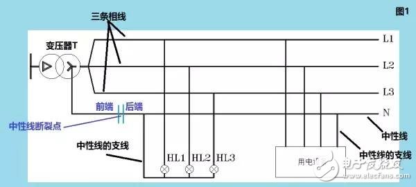
Note that the protective neutral line does not appear in Figure 1, only three phase lines L1/L2/L3, and the neutral line N of the three phase lines. The voltage of the three phase lines to the N line is 220V, and the voltage between the phase lines is 380V.
We know that the expression of the AC voltage is: 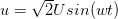 ,
,
The expression of the alternating current is:  .
.
Notice the fact that when the three phases are balanced , the voltage and current on the neutral bus have the following characteristics:

In Fig. 1, only the neutral line bus labeled with N is used for this characteristic, and the neutral line branch does not have this characteristic.
For a neutral spur, the current flowing through the neutral is equal to the magnitude of the phase current.
Let us look at Figure 1. The neutral line in Figure 1 is broken, so the voltage of the neutral line is still zero in front of the break point, but the voltage behind the break point is zero if the three phases are balanced; but if the three phases are unbalanced Then, the neutral line voltage after the break point will rise and the highest will rise to the phase voltage.
In fact, we found that as long as the three phases are unbalanced, the neutral line voltage will rise even though the neutral line does not break.
Let's look at Figure 2 and Figure 3:
In Figure 2, grounding is done at the neutral point of the transformer, which is referred to as system grounding in national standards and specifications. Note that the ground symbol here is the meaning of the earth.
There are two meanings of system grounding:
The first meaning: the system is grounded so that the potential of the neutral line of the transformer is forcibly clamped to the zero point of the earth ;
The second meaning: provides a channel for the system's ground current ;
It is worth noting that the N line in Figure 2 has a working ground, so its symbol has also changed to become PEN, which is the protection neutral in the main subject.
Protecting the neutral line here, protection takes precedence over the neutral line function.
From the foregoing discussion, we have known that if the protective neutral line breaks, the protective neutral line voltage at the rear of the break point may rise because the protective neutral line has a neutral line function.
In fact, the voltage at the back of the protective neutral breakpoint is completely determined by:

It can be seen that if  ,
,  with
with  Different, the three-phase voltage is unbalanced, protective neutral voltage
  Of course, it is not equal to zero.
Similarly, we can see that the current at the back of the protective neutral breakpoint is also related to the three-phase imbalance.
Looking at Figure 3, we find that the multi-point grounding method is adopted in the protective neutral line PEN to avoid the rise of the voltage at the rear of the protective neutral line break point.
Note that the grounding system corresponding to Figure 2 is called TN-C, and the grounding system corresponding to Figure 3 is called TN-CS.
Now, we can answer the question of the subject.
Let's look at Figure 4:
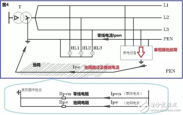
The exact name of the zero line is to protect the neutral line.
In Figure 4, the neutral point of the transformer is grounded, and the outer casing of the electrical equipment is directly grounded.
In normal operation, we see that there is no current flowing through the casing of the electrical equipment.
Now, let's analyze the case where the L3 is in contact with the shell of the electrical equipment.
The first thing we encountered was the basic parameter of how large the grounding resistance of the case is. In the national standard GB50054 "Low-voltage power distribution design specification" , the resistance of the grounding of the outer casing and the grounding resistance are called grounding resistance, and its value is not to be greater than 4 ohms. However, in engineering, the grounding resistance is generally considered to be 0.8 ohms.
Second, we need to know what the resistance of the protective neutral cable is. This value can be considered based on specific line parameters. For convenience, it may be stipulated that the length of the protective neutral cable is 100 meters, the cable core cross section is 16 square millimeters, and its operating temperature is 30 degrees Celsius, its resistance is:

With these two data, we can do the actual calculations.
Looking at the lower diagram of Figure 4, we find that when L3 is short-circuited to the housing of the consumer, there is current flowing through the protective neutral and current flowing through the ground.
It is noted that the protective neutral resistance and the grounding resistance are in parallel. According to the electrical physics knowledge of middle school, we know that the current of the parallel circuit is inversely proportional to the resistance of the resistor, namely:
 . From this:
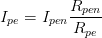 ----------------Formula 1
From Equation 1, we see that the ground current is related to the ratio of the protective neutral resistance to the ground resistance. We take the grounding resistance to 4 ohms and substitute the specific parameters to get the ground current:
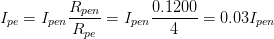 .
.
Even if we follow the engineering practice, the grounding resistance is 0.8Ω, and the ground current is:
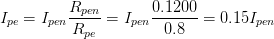 .
.
In other words, the ground current is only 3% to 15% of the protective neutral current! We take the intermediate value, then the ground current is only 6% of the protective neutral current.
The exact name of the zero line is to protect the neutral line.
At this point, we have already answered the question of the subject.
two
Now, let me ask a question:
After the case of the electrical equipment is faulty, the ground current is so small that it is almost negligible compared with the protective neutral current, so the electrification of the electrical equipment will exist for a long time. As a result, personal injury accidents will inevitably occur.
So, in the actual wiring, how do we protect personal safety?
Note: This issue is a bit wide, related to the grounding form of the low-voltage distribution network, related to the protection of the electrical equipment and the protection of the grounding, and the use of circuit breaker protection or leakage switch protection in the TN-C system. related.
Answer: From the above description, we can see that when a single-phase ground fault occurs, the ground current is small, which is not enough to drive the circuit breaker or fuse to perform protection. How to do it?
The International Electrotechnical Commission IEC proposed a solution, which is the grounding system .
Before we describe it in detail, let's clarify a few concepts:
The first concept, what is system grounding or working grounding?
System grounding (working grounding) refers to the neutral point of the power transformer, denoted by T, and is not represented by I.
The second concept, what is called protective grounding?
Protective earthing refers to the direct grounding of the electrical equipment's outer casing, indicated by T. If the enclosure is connected to a protective neutral or ground from the power supply, it is indicated by N.
The third concept, what is the grounding form?
There are three types of grounding, TN, TT and IT. TN is further divided into TN-C, TN-S and TN-CS.
After knowing these concepts, let's take a look at the original drawings given by the IEC on the TN-C and TT systems. Note that these two figures are unquestionable and are the authoritative interpretation of the grounding system.
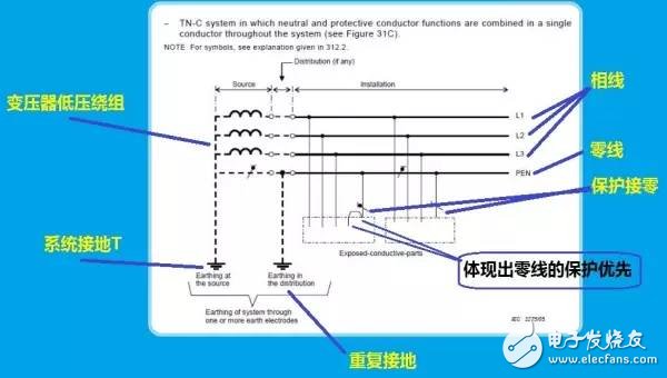
First picture: TN-C grounding system and TN-S system
The exact name of the zero line is to protect the neutral line.
This picture has appeared many times in the know.
Since the system is grounded in the circuit, but the load housing is not directly grounded, but is indirectly grounded through the protective neutral PEN, the grounding system is called TN-C.
The upper left corner of the figure is the low-voltage side winding of the transformer. We see that it leads to three phase lines L1/L2/L3 and one PEN protective neutral . Note that there are two groundings on the left side of the protective neutral . The first time at the neutral point of the transformer, this is called system grounding, and the second time in the middle is called repeated grounding. The meaning of repeated grounding is to prevent the voltage rise of the protective neutral line at the rear after the protective neutral line breaks.
It is worth noting the load. We see that the intermediate load PEN is first introduced to the enclosure and then to the protective neutral terminal. This shows that the protective neutral PEN is protection priority. So,
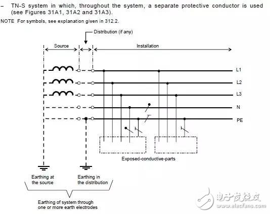
The picture below is the TN-S system, I will not explain:
Second picture: TN-CS grounding system
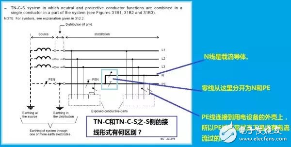
The difference between TN-CS and TN-C is that PEN is separated into N neutral line and PE protection line after repeated grounding.
Note that the case of the -S side load of the TN-CS is connected to the PE line, and the -C side of the TN-CS is connected to the PEN line, so the former is the protective ground and the latter is the protection zero. Compared to the two, the protective neutral can not be interrupted, and the PE line can not be interrupted.
TN-CS is very common in home distribution systems and distribution systems in schools and enterprises.
Third picture: TT grounding system
From the symbol code, the TT grounding system has system grounding, but its protective grounding is achieved by direct grounding.
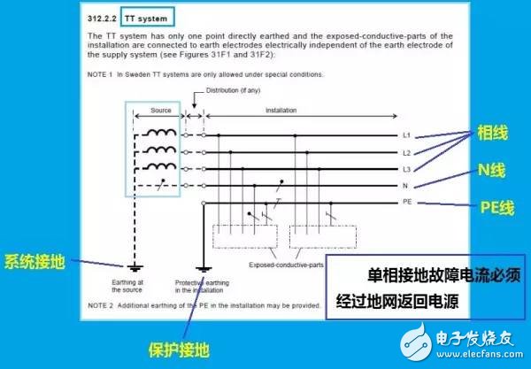
The neutral point of the TT grounding system transformer is directly grounded, and the outer casing of the electrical load is also directly and directly grounded. Form a protective ground.
It is worth noting that we have already described above. When a single-phase ground fault occurs, the current flowing through the ground grid is actually only about 6% of the N-line current. Therefore, the single-phase ground fault current occurring under the TT system is much smaller than the TN.
Now let's compare the similarities and differences between the TN system and the TT system :
1. For the TN system and the TT system, since the initials are all T, both systems have system grounding;
2. Since the N-line and PE lines of the TN system are connected together at the system ground or the repeated ground, the PENs are completely merged together, and the housing of the electrical equipment is directly connected to the PE or PEN, so the bill occurs. When the phase is faulty, the fault current will be relatively large, which is similar to the short circuit of the phase line to the N line. Therefore, the TN system is also called a large current grounding system;
The system ground of the TT is completely independent of the protection ground. The single-phase ground fault current must be returned to the power supply, must pass through the ground network, and the current is small. Therefore, the TT system is also called a small current grounding system.
With the explanation of the grounding system, we can answer the question.
1. Need to properly amplify the ground current
Properly amplifying the ground current so that the front-end circuit breaker of the consumer can perform an overcurrent protection operation, which is a TN system with a large ground current.
2. Install the leakage protection device RCD.
Let's look at Figure 5:
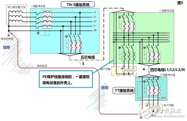
In Figure 5, we see that the neutral point of the transformer is directly grounded, then separated into N and PE, and the PE extends all the way to the load side and to the housing of the consumer. Therefore, this grounding method belongs to the TN-S grounding system.
When the electrical equipment is bumped, the resistance of the PE line is of course smaller than the grounding resistance, and the front end of the PE is also connected to the N line. The ground current is amplified to a short-circuit current close to N, which is the closest to the electrical equipment. The upstream circuit breaker performs overcurrent trip protection.
In Fig. 5, we also see that three phase wires and N wires are led from the four-core cable for secondary power distribution to the load side, the PE wire is cut off, and the outer casing of the electric equipment is directly grounded. Therefore, when the electrical equipment encounters a shell accident, the ground current can only be returned to the power supply through the ground network. This grounding method belongs to the TT grounding system under the TN-S.
Since the grounding current through the grounding grid under TT is small, both the IEC and national standards stipulate that the leakage protection device RCD must be installed.
The principle of RCD is as follows:
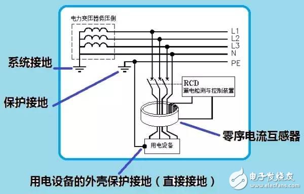
When a single-phase ground fault does not occur, the phasor sum after the three-phase current is combined with the N-line current is zero. When a leakage occurs, a phase current increases, and the leakage current returns to the power supply through the ground grid, and the N-line current remains the same as before. Thus, a magnetic flux will appear in the magnetic circuit of the zero-sequence current transformer, and of course the current will appear in the measuring winding, and the detection and control components are driven to cause the front-end circuit breaker to perform the leakage protection action.
The RCD's operating current can be below 30 mA, effectively protecting personal safety.
The Cutting Machine is a product developed for Cutting TPU Protective Films, Hydrogel Screen Protective Films and PVC Back Stickers.
Advantages of Cutting Machine:
1. "0" inventory, no need to worry about large inventory.
2. Compatible with "99%" 6000+ mobile phones, watches, tablets, etc.
3. According to needs-customize the Protective Film that customers want at any time.
4. Will not lose sales opportunities due to shortages.
5. Save product packaging and transportation costs.
6. Say goodbye to the losses caused by unsold old inventory.
7. No need to spend time and energy to find various types of products.
8. Selling new products for the first time.
9. Different styles of Protective Film can be customized.
10. Simple operation, align and paste it on the device, just one step.
11. Green environmental protection, reduce packaging, reduce waste and reduce costs.
12. To meet the needs of more customers.
13. Add value and increase sales for mobile phone stores, offline stores, and value-added services.
14. Exclusive policy, regional guarantee, first come first served.
15. Lead opponents, lead the market, and seize opportunities.
16. Regain retail market share and create higher value space.
17. New generation mobile internet Mobile Phone Protective Film customization system.
18. Quickly start the business model and start the retail business easily.
Hydrogel Cutting Machine, Mobile Phone Screen Protector Cutting Machine, Hydrogel Film Cutting Machine, Hydrogel Protective Film Cutting Machine, Hydrogel Machine
Shenzhen Jianjiantong Technology Co., Ltd. , https://www.jjthydrogelprotector.com