With the declining fossil energy sources and the excessive emissions of greenhouse gases, global warming has become more and more important. On the one hand, people are actively developing various types of renewable new energy, on the other hand, they are also advocating green energy conservation and emission reduction. Environmental technology. As an inexhaustible and clean energy, solar energy has become an important representative of many renewable energy sources. In the field of lighting, long-life, energy-saving, safe, green, colorful, and miniaturized LED solid-state lighting has also been Recognized as an important way of energy conservation and environmental protection in the world. The solar-LED streetlight combines the best of both worlds with clean energy and high-efficiency LEDs for green lighting.
The solar-LED street light scheme introduced in this paper can automatically detect ambient light to control the working state of street lamps. Maximum power point tracking (MPPT) ensures maximum solar panel efficiency, constant current control LED, and battery status output and user can set Set the LED working time and other functions.
At present, street lamps generally use a high-voltage sodium lamp structure powered by a mains supply. The electronic drive part of the high-pressure sodium lamp needs to convert the mains from AC to DC, and then inverter to AC to drive, resulting in low system efficiency; Mains need to lay complex and expensive pipelines. Solar-LED street lights do not have the above problems. Because solar panels output DC power, and LEDs are DC-driven light sources, the combination of the two can improve the efficiency of the entire system; the use of solar energy also eliminates the need to lay cables and The cost of its related works.
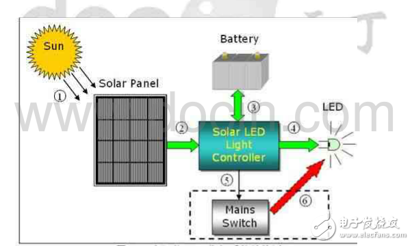
Figure 1: The structure of the solar-LED street light system.
Figure 1 is a schematic view of the structure of a solar-LED street light. When the solar panel is illuminated by sunlight, its internal PN junction will form a new pair of electrons and holes, and a DC current will be generated in one loop; this current will flow into the controller and will charge the battery in some way. The battery will be recharged during the day and energy will be supplied to the LED at night. The operation of the LED is performed by the controller. While ensuring the constant current operation of the LED, the controller also monitors the state of the LED and controls the working time. In the case of continuous rainy days and insufficient battery power, the controller will send a control signal to activate the external mains supply system (not included in the controller) to ensure the normal operation of the LED. The external mains supply system is only used as a backup energy source and will only be used if the battery has insufficient power. Charging the battery is done entirely by solar energy to ensure maximum use of solar energy.
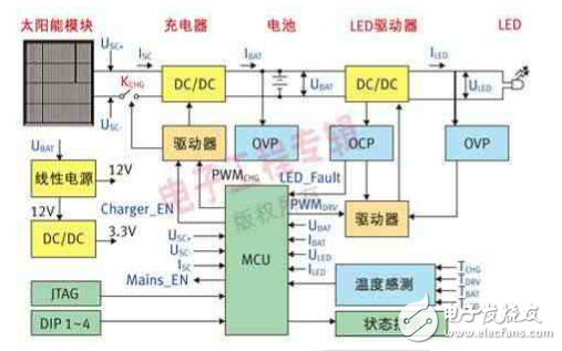
Figure 2: Block diagram of the controller structure
2 is a block diagram showing the structure of the controller. When the solar panel comes in, it will first be connected to the DC/DC converter (battery charging circuit) through a switch MOS tube KCHG. The output of this converter is connected to the two ends of the battery (the actual circuit will be connected to the battery through a fuse first). ). In addition, KCHG has two functions: one is to prevent the reverse charging flow from the battery when the output of the solar cell is low; the other is to protect the circuit when the polarity of the solar panel is reversed. The DC/DC converter adopts a buck topology, and the topology selection must consider not only the maximum power point voltage of the solar panel and the maximum voltage of the battery, but also the efficiency and cost. The battery and the LED are also passed through a DC/DC converter (LED drive circuit), and the LED is controlled by a constant current. Considering the fluctuation range of the battery voltage and the operating voltage range of the LED, a flyback topology is used in the design circuit. Structure to ensure constant current output. The efficiency of the flyback topology is generally not as simple as the boost or step-down circuit. If you want to improve the efficiency of the system, you can use the boost or step-down circuit by optimizing the relationship between the battery voltage and the LED voltage to improve efficiency and possibly further reduce cost.
The control of the whole controller is realized by an MCU. The main work of the MCU includes the following points: First, the MPPT algorithm is used to optimize the working efficiency of the solar panel; second, the appropriate charging mode is adopted for different states of the battery; The constant current output of the drive circuit; the fourth is to judge the day and night to switch the battery charging and discharging mode; the last is to provide monitoring protection, temperature monitoring, status output and user control input detection (DIP1~4). The choice of MCU is mainly to meet the needs of ADC, GPIO and external interrupts, and does not need to pursue speed alone. Table 1 lists the use of MCU peripherals in the actual circuit. Considering the need for future expansion, the main control chip uses STM32F101RXT6 (the latest STM32 series MCU from STMicroelectronics, using the Cortex-M3 core).
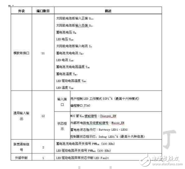
Table 1: MCU peripheral assignments.
Laptops,windows Laptops,win11 Laptops,win10 Laptops
Jingjiang Gisen Technology Co.,Ltd , https://www.gisentech.com