Shanxi Lanhua Coal Industry Group Co., Ltd. Tangan Coal Mine is a modern and well-developed mine under the orchid company. The predecessor of the branch, Tang'an Coal Mine, was built in the early days of the founding of the People's Republic of China. Before the establishment of the Orchid Group, it was a municipal coal mine in Gaoping City. It covers an area of ​​550,000 square meters and has a minefield area of ​​29.95 square kilometers. It belongs to the hinterland of Qinshui Coalfield, with a geological reserve of 339 million tons, an industrial reserve of 223 million tons, and a recoverable reserve of 137 million tons. The annual production capacity is 1.5 million tons.
The mine hoist is the key equipment of the coal mine, and it shoulders the heavy responsibility of transporting objects in the well. It is a large lifting machine. The motor is driven by the motor to drive the wire rope to drive the container up and down in the wellbore to complete the transportation task. The mine hoist is evolved from the original water lifting tool. The modern mine hoist has a large amount of lifting, high speed and high safety, and has developed into a fully automatic heavy mining machine controlled by electronic computers. The mine has the main shaft lifting and the auxiliary shaft lifting. The main lifting function is to upgrade the beneficial minerals (such as coal) along the wellbore. The mine hoist is mainly composed of electric motor, reducer, reel (or friction wheel) and brake. The system, depth indication system, speed limit system and control system are driven by AC or DC motor. According to the working principle of the lifting wire rope, the winding type mine hoist and the friction type mine hoist are divided. The main function of the auxiliary shaft lifting is to raise the meteorite along the wellbore, to lower the material, to lift personnel or equipment. Mine hoists play an important role in the production of coal mines.
Mine and hoist as one of the largest electrical equipment in the mine, its power consumption accounts for 30%-40% of the total electricity consumption of the mine, and the operating characteristics are complex, fast, and inertia. Once the hoist loses control, it cannot be given When the speed is running, it may cause major safety accidents such as overspeed and over-winding, resulting in equipment damage and even casualties, causing significant personnel and property losses to the mine.
The original auxiliary shaft hoist system adopts the AC motor rotor circuit series resistance speed regulation. Due to the low speed regulation accuracy, poor reliability and high maintenance cost of the system, the leaders of the Orchid Group Tangan Coal Mine have investigated the situation of using the hoist inverter on the domestic user site. It was decided to use the new scenery JD-BP37-280T (280KW/6KV) high-pressure hoist inverter to carry out system transformation of the auxiliary shaft hoist system. An alternating current motor is a machine that converts electrical energy into mechanical energy. The AC motor consists essentially of an electromagnet winding or distributed stator winding for generating a magnetic field and a rotating armature or rotor. The motor is made by the phenomenon that the energized coil is forced to rotate in a magnetic field. The AC motor consists of a stator and a rotor, and the stator and the rotor use the same power source, so the direction change of the current in the stator and the rotor is always synchronized, that is, the direction of the current in the coil changes, and the direction of the current in the electromagnet also changes. According to the left-hand rule, the direction of the magnetic force of the coil is unchanged, and the coil can continue to turn. The AC engine works by using this principle.
2 Overview of the original mine hoist system
2.1 system parameters
2.1.1 Mine hoist
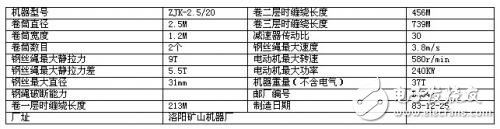
2.1.2 reducer
2.1.3 three-phase asynchronous motor
2.2 AC motor rotor circuit string resistance speed control system
During the acceleration process, the AC contactors KM1, KM2, KM3, and KM4 are step by step, and the rotor loop resistance is sequentially reduced to ensure that the average value of the acceleration torque is constant. If the motor is required to run at a low speed, a large resistance in the rotor circuit string is required. In order to solve the negative force requirement of the deceleration section, a dynamic braking scheme is usually adopted, that is, the high voltage power supply on the stator side is cut off, a DC voltage is applied, or a low frequency power supply is applied to the stator winding to operate the electric motor in the power generation state. AC contactors are widely used as breaking and control circuits for electric power. It uses the main contact to open and close the circuit, and the auxiliary contact to execute the control command. The main contacts generally have only normally open contacts, while the auxiliary contacts often have two pairs of contacts with normally open and normally closed functions. Small contactors are often used as intermediate relays in conjunction with the main circuit. The contact of the AC contactor is made of silver-tungsten alloy and has good electrical conductivity and high temperature ablation resistance. When the coil is energized, the static iron core generates electromagnetic attraction, and the moving iron core is sucked. Since the contact system is linked with the moving iron core, the moving iron core drives the three movable contact pieces to operate at the same time, and the contacts are closed, thereby being connected. power supply. When the coil is de-energized, the suction force disappears, and the moving core interlocking portion is separated by the reaction force of the spring, so that the main contact is disconnected and the power is cut off.
The problem with this drag scheme is:
(1) Open-loop stepped speed regulation, the acceleration is difficult to accurately control, and the speed regulation accuracy is poor;
(2) Contact control, large-scale use of large-capacity switches, large system maintenance workload, and poor reliability;
(3) The operating efficiency is low, and most of the power is consumed in the resistor at low speed;
(4) The mechanical characteristics of the motor are soft, and the power consumed by the general resistance is about 20%-30% of the output power of the motor;
(5) The contactor is often closed and disconnected, and the noise is relatively large. Although this speed control scheme has a simple control method and a low initial equipment investment, the technical performance and operation efficiency are low, and many medium and small mine hoists still adopt this speed control scheme.

Figure 1 Rotor loop series resistance speed control system
3 high voltage hoist inverter system principle
3.1 System Structure
The structure of JD-BP37 series high voltage variable frequency speed control system consists of phase shifting transformer, power unit and controller. The 6KV series has 18 power units, and each 6 power units are connected in series to form one phase.
3.2 power unit circuit

Figure 2 power unit circuit
Each power unit is structurally identical and interchangeable. The main circuit structure is shown in Figure 2. It is a basic AC-DC-AC bidirectional inverter circuit. In the figure, the three-phase full-bridge mode rectification is performed by the rectifier bridge, and the rectified filter capacitor is charged to determine the bus voltage, and the single-phase inverter is realized by performing sinusoidal PWM control on the IGBT inverter bridge in the inverter block B. When the motor enters the power generation state, the diode in the inverter block B completes the freewheeling, and then full-wave rectification, so that the energy can be transferred to the filter capacitor. As a result, the bus voltage rises to a certain extent, and then the inverter block A is started. The SPWM inverter is performed, and the input inductor returns to the secondary pole of the phase shifting transformer, and the energy is fed back to the grid through the transformer. The SPWM (Sinusoidal PWM) method is a relatively mature one, and currently uses a wider PWM method. An important conclusion in the aforementioned sampling control theory is that the effects of the narrow impulses with equal impulses and different shapes are basically the same when they are applied to the inertia. The SPWM method is based on this conclusion. The PWM waveform, which is equivalent to the sine wave, and the SPWM waveform, which is equivalent to the sine wave, is used to control the on/off of the switching device in the inverter circuit to make the area of ​​the pulse voltage output. It is hoped that the output sine wave has the same area in the corresponding interval, and the frequency and amplitude of the output voltage of the inverter circuit can be adjusted by changing the frequency and amplitude of the modulated wave.
3.3 input side structure
The secondary winding of the phase shifting transformer in this machine is divided into three groups to form a 36-pulse rectification mode; this multi-stage phase-shifting superimposition method can greatly improve the current waveform on the grid side, so that the power factor of the grid side under load is close. 1, the input current harmonic component is low. It is measured that the total relative harmonic content of the input current is less than 4% under the rated input voltage rated current of 90%-105%.
In addition, due to the independence of the secondary winding of the transformer, the main circuit of each power unit is relatively independent, similar to the conventional low-voltage inverter, and it is easy to adopt the existing mature technology.
3.4 output side structure
The output side is connected to each other by the U and V output terminals of each unit to form a star connection to supply power to the motor. By recombining the PWM waveform of each unit, the stepped PWM waveform shown in Figure 3 can be obtained. This waveform has a good sinusoidality and a small dv/dt, which can reduce the insulation damage to the cable and the motor. The output cable can be made long without the need of an output filter. The motor does not need to be derated, and can be directly used for the modification of the old equipment. At the same time, the harmonic loss of the motor is greatly reduced, the mechanical vibration caused thereby is eliminated, and the mechanical stress of the bearing and the blade is reduced.

Figure 3 Line voltage ladder PWM waveform output from the inverter
3.5 controller
The controller is a master device that changes the wiring of the main circuit or the control circuit in a predetermined order and changes the resistance value in the circuit to control the starting, speeding, braking, and reversing of the motor. The controller is the command and control center of the whole CPU. It consists of three parts: instruction register IR (InstructionRegister), program counter PC (ProgramCounter) and operation controller 0C (OperationController), which is very important for coordinating the orderly work of the whole computer.
The controller core is implemented by a high-speed 32-bit digital signal processor (DSP) operation, and a well-designed algorithm ensures optimal motor performance. The man-machine interface provides a friendly all-Chinese WINDOWS monitoring and operation interface, and can realize remote monitoring and network control. The built-in PLC controller is used for the logic processing of the switch signal in the cabinet, and the coordination with various operational signals and status signals in the field. It can be flexibly interfaced with the user site to meet the special needs of the user and enhance the flexibility of the system.
Digital signal processors (DSPs) have great advantages over analog signal processing in terms of high precision, flexibility, reliability, ease of integration, and ease of storage. Digital signal processing is an emerging discipline that covers many disciplines and is widely used in many fields. Since the 1960s, with the rapid development of computer and information technology, digital signal processing technology has emerged and developed rapidly. Digital signal processing is a method of processing real-world signals by performing transformations or extracting information using mathematical techniques, and these signals are represented by a sequence of numbers. In the past two decades, digital signal processing has been widely used in communications and other fields. High-performance DSP not only has fast processing speed, but also can realize real-time input and output of data without interruption. The DSP structure is relatively simple, and assembly programming is generally used. The predictability of processing completion time is much stronger than that of a conventional microprocessor with complicated structure and instructions and relying on the compiler system.
Outdoor Fixed LED Display is a popular product for its high quality, every year sold to at least 80,000 pieces around the world, including Europe, North America, southeast Asia.Compared to other indoor LED display in the market, its biggest advantage is that it can display high-definition images while maintaining low power consumption.Besides, it adopts Die casting aluminum cabinet which is ultra-thin and ultra-light and owns good heat dissipation.Easy to install and maintain and suitable for multiple indoor scenes.
Application:
* Business Organizations:
Supermarket, large-scale shopping malls, star-rated hotels, travel agencies
* Financial Organizations:
Banks, insurance companies, post offices, hospital, schools
* Public Places:
Subway, airports, stations, parks, exhibition halls, stadiums, museums, commercial buildings, meeting rooms
* Entertainments:
Movie theaters, clubs, stages.
Outdoor Fixed LED Display,Led Wall Display Screen,Curved Led Display Screen,Led Display Board
Guangzhou Chengwen Photoelectric Technology co.,ltd , https://www.cwstagelight.com