Several good FET tube amplifier circuit diagrams
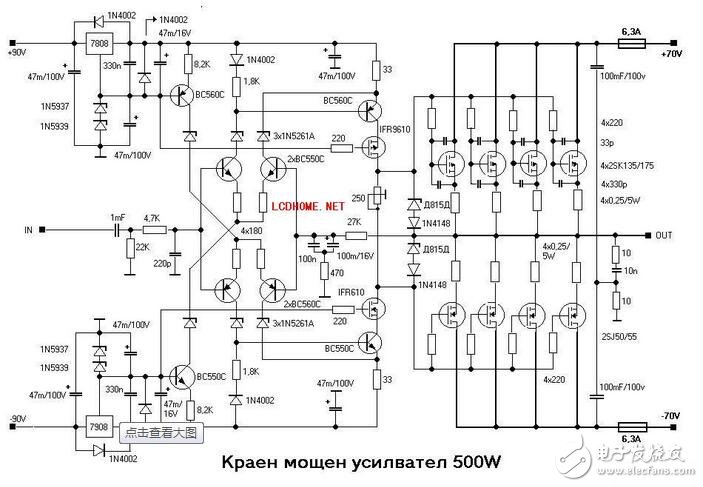
The FET multi-tube parallel output, 500W.
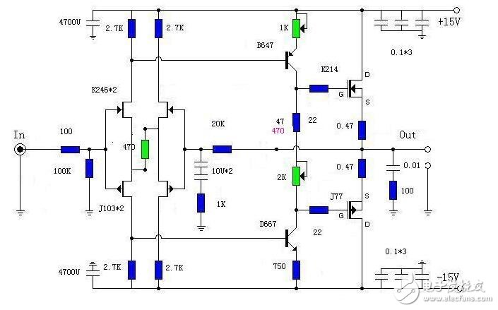
The biggest difference between the field tube and the general power is that the field tube is driven by voltage. It is different in the driver level. Without the field tube amplifier, how to look at your design and craft!
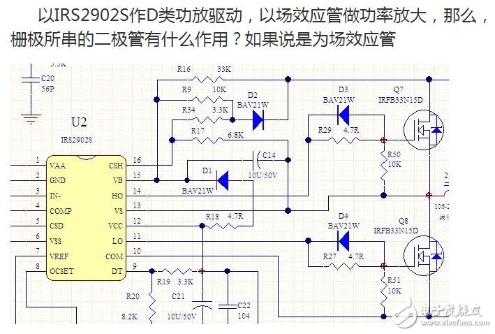
IRFB33N15D is a very good MOS tube with a low internal resistance of 56mΩ, a maximum current of 33A, and a withstand voltage of 150V. It is commonly used in DC/DC converters. Of course, it is also frequently used in digital power amplifiers. .
It also has its shortcomings. Its input capacitance is 2020pF. Like the common MOS tube, it is driven by a special circuit when driving it. Like the R29 and D3 parallel circuits in your circuit, it is also the industry's usual method. The role is:
When there is no R29, the gate of Q7 is directly connected to the front IC pin, and the inside is a totem pole circuit. Because it is a capacitive load, there will be oscillation, which causes the driving waveform to ring, and the resulting time is The MOS tube is not opened enough, the internal resistance is large, and the efficiency is low. Stringing into R29 eliminates this oscillation, and the time constant of the subsequent MOSFET input capacitor (Ciss) is much smaller than the turn-on time of the MOS transistor by 13ns, while the 4.7Ω 2020pF time constant is 9.5nS, which satisfies the requirements.
When IRFB33N15D is driven by standard circuit (equivalent to R29 is 3.6Ω), its recovery time is up to 130nS, which is also a common problem of MOS tube. In order to speed up the shutdown (to fight for this 9.5nS time), it is desirable to turn off the gate when shutting down. The resistance is zero, so the Schottky diode D3 (which can operate at approximately GHz) is reverse-connected on R29 to accelerate the discharge.
The VGS of IRFB33N15D is between 3.0V and 5.5V. Actually, depending on the operating voltage of IRS2902S, it is actually around 10V. The forward voltage drop of Schottky diode D3 is only about 1.2V (current 1A, but its ΔV /ΔI is about 0, the dynamic internal resistance is extremely low), and it is already ensured that Q7 and the gate are below VGS, which has no effect on shutdown. In addition, you should learn the meaning of dynamic internal resistance, like the power supply, the voltage drop may be 5V, but its internal resistance can be as low as ten milliohms.
The two FETs in this circuit cannot be turned on at the same time. Therefore, when they work, they should be turned off first and the conduction should be slow. D3, D4 diode can quickly release the gate junction voltage of the FET when the driving voltage drops, so that the time for the tube to return from the on state to the off state is greatly shortened. When the driving voltage rises, the gate junction capacitance of the tube is charged through R29 and R27, thereby delaying the conduction time of the tube. In this way, the shutdown priority is achieved, and the conduction is slightly slowed, which greatly avoids that one tube has not exited conduction, and the other tube has entered a conducting state.
2)High speed custom labeling and printing on flanges available – even on short runs
3)One piece molded construction for strength and precision
4)Appealing designs as well as ergonomics (no sharp edges)
| Type |
Weight (gram) |
d1 (mm) |
D1 (mm) |
d2 (mm) |
D2 (mm) |
H1 (mm) |
H2 (mm) |
d3 (mm) |
A1 (mm) |
A2 (mm) |
d4 (mm) |
E (mm) |
| PC-70 | 40 | 70 | 38 | 70 | 85 | 20 | 7 | 7 |
|
|
||
| PC-80 | 70 | 80 | 50 | 64 | 80 | 20 | 8 | 8 | 7 | 20 | ||
| PC-83 | 70 | 83 | 45 | 100 | 120 | 20 | 10 | 10 |
|
|
||
| PC-100A | 110 | 100 | 45 | 70 | 88 | 20 | 9 | 9 |
|
|
||
| PC-100B | 100 | 100 | 45 | 100 | 120 | 20 | 10 | 10 |
|
|
||
| PC-125A | 180 | 125 | 65 | 100 | 120 | 20 | 10 | 10 | 7 | 20 | ||
| PC-125B | 170 | 125 | 70 | 100 | 120 | 20 | 10 | 10 |
|
|
||
| PC-130A | 200 | 130 | 65 | 100 | 120 | 22/25 | 10 | 10 |
|
|
||
| PC-130B | 210 | 130 | 65 | 100 | 120 | 22 | 10 | 10 |
|
|
||
| SH-16 | 230 | 150 | 90 | 100 | 124 | 30 | 12 | 12 | 12 | 26 | ||
| PC-185A | 400 | 185 | 128 | 155 | 178 | 30 | 11 | 11 |
|
|
||
| PC-185B | 500 | 185 | 128 | 155 | 178 | 30 | 11 | 11 |
|
|
||
| PC-185C | 500 | 185 | 130 | 160 | 180 | 30 | 10 | 10 |
|
|
||
| PC-220A | 660 | 220 | 110 | 155 | 185 | 40 | 15 | 15 | 12 | 42 | ||
| PC-220B | 660 | 220 | 110 | 155 | 185 | 38 | 15 | 15 | 15 | 38 | ||
| PC-220C | 660 | 220 | 110 | 155 | 185 | 30 | 15 | 15 | 14 | 38 | ||
| PC-250 | 870 | 250 | 110 | 155 | 185 | 40 | 15 | 15 | 12 | 42 | ||
| PC-300A | 1400 | 300 | 180 | 170 | 200 | 32 | 15 | 15 | 17 | 45 | ||
| PC-300B | 1400 | 300 | 180 | 170 | 200 | 100 | 15 | 15 | 20 | 125 | ||
| PC-355 | 1950 | 355 | 224 | 160 | 200 | 36 | 20 | 20 | 26 | 50~80 | ||
| PC-410 | 4550 | 410 | 310 | 180 | 228 | 70 | 24 | 24 |
|
|
||
| PC-500A | 8450 | 500 | 315 | 180 | 250 | 40 | 35 | 35 | 26 | 70~100 | ||
| PC-500A1 | 8450 | 497 | 315 | 180 | 250 | 40 | 35 | 35 | 26 | 70~100 | ||
| PC-500B | 8600 | 500 | 250 | 250 | 300 | 56 | 25 | 25 | 26 | 70~100 | ||
| PC-500B2 | 9020 | 500 | 250 | 240 | 290 | 40 | 25 | 25 | 26 | 70~100 | ||
| PC-500C | 8600 | 500 | 250 | 235 | 300 | 56 | 20 | 20 | 26 | 70~100 | ||

Wire Packaging Spool, Magnet Wire Reel, Magnet Wire Spool, Packing Wire Spool
NINGBO BEILUN TIAOYUE MACHINE CO., LTD. , https://www.spool-manufacturer.com