In the field of industrial automation, a large number of smart devices can be connected to the Internet through various channels. The information and data are transmitted to each other through the network, to realize the autonomy of the functions of intelligent field devices, the highly decentralized system structure, and the integration of supervision and control. .
FieldBus is a new technology developed in response to this situation. The emergence of fieldbus marks the beginning of a new era in industrial control technology. The development of this technology has greatly promoted the realization of a device-oriented automation system. Compared with the traditional distributed control system (DCS), he has the advantages of full openness, full decentralization, and interoperability, but it still has a lot of limitations, mainly in the following aspects:
1. Current field instruments and equipment have low computing power and information processing capabilities, and the complex control functions are still concentrated on one control computer, which cannot achieve full decentralized control and there is a risk of concentration.
2. Fieldbus is only a part of the system and is located at the bottom of the system, which is not enough to achieve the system's full open architecture. The system architecture is vertical and there is a bottleneck in data communications.
3. The IEC61158 standard includes eight types of field buses, which are quite different from each other and cannot realize interoperability. There are certain difficulties in connecting to each other.
4. All the controllers in the system operate independently and each performs independent data processing. It is difficult to share all the information and the real-time performance of the system is not satisfactory.
The above explanation shows that the traditional classic PLC and fieldbus technology are no longer suitable for this requirement. Even technologies such as industrial PCs and OPCs can only marginally improve the functionality of the system as long as they are embedded in the traditional system structure.
Therefore, in order to reduce heavy programming work and achieve simplification of the system, it is necessary to change the structure of the system. With the continuous development of information technology, there will inevitably be a control strategy in the field of industrial control that can make up for the defects of the field bus and realize a unified, efficient and real-time control system. Industrial Ethernet is a control technology that has rapidly developed to meet this need. Among all network technologies, Ethernet technology is the best choice so far. He can meet all of the following requirements:
1. Taking full account of future development needs, it has a high transmission rate and currently reaches 100 Mb/s.
2. High transmission security and reliability, hub technology certainty.
3. The application of the hub does not need to consider the expansion of the network.
4. A standard was established: a new industrial control bus standard.
5. Connected with IT, the application of "world standard" TCP/IP technology.
6. Random network access technology throughout the entire network.
Ethernet (Ethernet) is both a technique for computers to access the local area network. Due to the significant increase in Ethernet transmission rates, the industrialization of physical layer standards and the formation of Ethernet hub technology, the emergence of Gigabit Ethernet technology and collision-free full-duplex fiber optic technology, this advanced network technology has been advanced to an earlier stage. Industrial Ethernet technology is formed in industrial control networks that are considered unsuitable. Compared with the current fieldbus-based control network, the control network based on industrial Ethernet technology is a low-cost (many commercial Ethernet chipset and technology can be borrowed), high-performance control network solutions.
Second, the program analysis
(I) Design of embedded industrial Ethernet control system
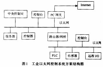
The control system network is divided into three layers: information layer, control layer, and device layer (sensing/execution layer). Traditional control systems mostly use Ethernet at the information layer, and generally use different field buses or other private networks at the control layer and device layer. At present, almost all PLCs and remote I/O vendors can provide products that support TCP/IP Ethernet interfaces. With the Ethernet architecture, the controller's location can also break through the limitations of traditional network architectures, either on-site or in the central control room. Current controllers and even remote I/O support for Ethernet are becoming more and more powerful. Web servers have been integrated in some controllers and remote I/O modules, allowing users at the information layer to be as direct as users at the control level. Get the current status values ​​in the controller and remote I/O modules.
In this scenario, the network control system is divided into three parts:
1. Field device layer
Including embedded node control module and field work machine. The former mainly completes the collection of on-site data, processing and preservation of front-end data, and communicates with the upper layer through the Internet interface. The control module can implement server functions, and the information layer can be accessed via Web browsing (supporting point-to-multipoint communication). The latter is mainly responsible for some auxiliary and monitoring matters, such as field data transmission, historical data processing, and report output.
2. Internal information layer
It is mainly composed of internal Ethernet. It mainly completes the information collection and distribution of the entire system. That is, it accesses the Web server in the site node control module, and the data of all monitoring nodes under monitoring is centralized on the LAN server through the HUB hub, and is managed and saved uniformly. The way of browsing is released to the upper management department.
3. Internet network layer
This layer is connected to each LAN of the enterprise through switches and routers to complete the global release of information. The department located in the office can intuitively see the work status, production plan completion, and equipment working status of the site. Even if they are thousands of miles away, they can go anywhere. To master the operation of the company (company), so that the remote office really become a reality. The industrial Ethernet control system scheme is shown in Figure 1.
(II) Implementation of embedded interface control module
In the industrial Ethernet architecture, Ethernet is used as the system bus to connect the intelligent control module. There is no difference between internal and external data communication. Hub technology is integrated in each controller and separates internal communications from external communications by allocating address space. The integration of the hub technology and the underlying protocol ensures the certainty, compatibility and integrity of the Ethernet. At present, the protocols at the transport layer and the network layer have basically been unified. TCP/IP has become the standard network protocol. This is the “hub†for the normal operation of Ethernet. The key link in the technology of industrial Ethernet is: implement the TCP/IP network communication protocol in the field-level node control module (such as a remote I/O module), ie establish a protocol stack. With the rapid development of electronics and information technology, it has become possible to embed TCP/IP protocols into node modules through software or hardware. The software way embeds TCP/IP in the ROM of the microprocessor, the hardware way is to design the embedded processor and ASIC device chip and use as the network interface directly.
The program adopts a MCU based on RISC structure, with on-chip Flash program memory, with system programming and debugging functions. Due to the CPU parallel pipeline method and single clock cycle instructions, the instruction execution speed can reach 100 MI/s under the 100 MHz crystal drive. All I/O pins can be configured flexibly through programming. Based on the above characteristics, a virtual peripheral (Virtual Peripheral) function can be realized: the CPU implements hardware peripheral functions (such as UART, I2C, SPI, CallerID, FSK, etc.) by directly executing ordinary virtual I/O ports by executing a virtual software module. The most special is that this feature can be used to implement popular Internet protocol stacks, such as HTTP, SMTP, POP3, TCP, UDP, ICMP, IP, PPP.
The implementation of the node module adopts the multi-task mode, and the single-chip microcomputer can complete the Internet protocol processing while performing data acquisition or completing I/O control tasks. At the application layer, you can select any of HTTP, SMTP, and POP3 as the communication protocol between the SCM system and the Internet remote management terminal; or develop other programs based on TCP and UDP protocols as application layer software. Using the Ethernet control chip, the data packet can be sent to the Ethernet and the Internet can be accessed via Ethernet to implement a true embedded TCP/IP device. Figure 2 shows the structure of the control module.
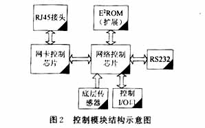
RJ45 interface with this system and LAN. The flow of data is: the request information comes from the local area network, is sent to the control chip of the network card through RJ45, after processing the data packet of 05 sends to the one-chip computer protocol stack, the data packet is analyzed by the protocol stack, get the original request information. The request information is then processed by the single-chip microcomputer to generate reply information. The process of replying information to the LAN is just the opposite.
Interface control module features:
1. Do not rely on PC or high-end microcontroller, truly 8b microcontroller system directly access the Internet, the entire system completely self-sufficient.
2. Use fewer peripheral devices and the system cost is low.
3. Support IP, TCP, UDP, ICMP, HTTP, SMTP protocol.
4. The system provides a 10/100 Base-T network interface and directly supports the Ethernet IEEE802.3 protocol.
5. Through the system's built-in RS232 serial interface and support for Web page download, real-time, dynamic display and control of monitoring point data.
(III) Development of Ethernet Communication Protocol
Ethernet is designed according to the requirements of the local area network. The Ethernet standard (IEEE 802.3) defines the physical layer and data link layer of the OSI reference model. Cable types, connectors, and signal levels are defined at the physical layer; the data link layer defines the frame format, error control methods, and channel assignment methods. But Ethernet can't complete the third layer of the OSI model. In this sense, he is not a complete network protocol. How to implement the network layer, transport layer, and application layer of the OSI model based on the existing protocol is the key to solve the problem.
The implementation principle of the network protocol stack is shown in Figure 3.
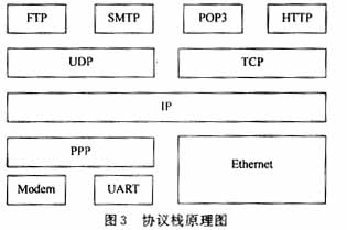
The software protocol stack in Figure 3 is written in microcontroller language and stored in the Flash program memory of the microcontroller. Different manufacturers at home and abroad have launched different industrial Ethernet protocols for their own Ethernet products. In general, protocol development is focused on the following three aspects:
1. Network layer protocol
The network layer mainly deals with the activities of packets in the network, such as the selection of packets and the determination of routes. Including: IP protocol (Internet Protocol), ICMP protocol (Internet Internet Control Message Protocol) and IGMP protocol (Internet Group Management Protocol). The IP protocol is the main application object. All data in the Internet is transmitted in the form of IP data packets. Its greatest feature is the provision of unreliable and connectionless datagram delivery services.
The protocol stack is developed in the embedded control module. The implementation of the IP layer is to IP packetize the message to be sent, that is, add the IP header to make it conform to the format of the IP data packet and send it to the physical layer; it will be received from the physical layer. The layer data packet is IP unwrapped, that is, the packet header is removed and sent to the TCP layer.
2. Transport layer protocol
TCP provides a connection-oriented, reliable byte stream delivery service that is retransmitted by TCP once the datagram is corrupted or lost. In the embedded module stack, the implementation of the TCP layer is implemented through the provided TCP API (application program interface).
3. Application layer protocol
HTTP is a protocol on the WWW. When a user wants to browse a web page on the server, HTTP requests are sent from the user's browser to the HTTP server. The server responds to this request and sends the specified web page back. The user sees the web page. Because the HTTP layer is below the TCP layer, that is, HTTP uses TCP as its transport protocol, the above two TCP connections are also used by WebServer. Of course, the TCPAPI send and receive functions are also used to implement WebServer requests and corresponding commands to complete the data transfer.
In the control module, a Web server can be constructed using the HTTP protocol, a mail service client can be constructed using the SMTP protocol, a point-to-point system can be constructed using the PPP protocol, and a C/S model can be finally established. All server resources are stored in external memory (E2PROM). Its capacity determines the size of WebServer's resource file. HTTP uses a Uniform Resource Locator to specify network resources (such as HTML, text documents, images, Java scripts, Java applets, PDF documents, etc.) returned to the client. Any type of Web server in the network can communicate with it interactively to achieve remote, real-time control.
(4) Development of System Application Platform
The development of industrial control application software is mainly based on the B/S network architecture. The control layer establishes the intelligent node module to realize the collection of on-site data information and establishes the Web resource server. The client only needs to read it through the browser in real time. Data, and control commands can be communicated. This application system focuses on the development of the underlying server. At the same time, the system's monitoring software adopts a networked design, with good scalability and interconnection, with centralized display of parameters, real-time data inquiries, and other special functions brought about by the networking of all devices such as: automatic switching of control modules, Network failure detection, resource sharing, etc.
Third, the conclusion
The rapid development of network technology has profoundly affected the transformation of industrial automation technology. Embedded Industrial Ethernet, a highly-open, flexible, and powerful new industrial control network, will connect enterprise field device layer, control layer, and management layer with high efficiency to form network integration automation. Basic enterprise information system. He will infiltrate all aspects of manufacturing such as machinery manufacturing, automobile manufacturing, semiconductor manufacturing, petrochemical, etc., and will also be widely used in building automation, power system monitoring, robot control, textile packaging, printing, etc. All need digital information exchange and Integrated areas. Therefore, taking industrial Ethernet as a brand-new "field bus" is the inevitable choice for future industrial control networks. He realized the seamless connection between the field device layer and the enterprise intranet (Intranet). While establishing a truly unified industrial control network, he applied open ideas to the industrial control network to a higher degree.
Economical Channel type fiberglass flexible Cable support tray Application
- Frp Cable Tray is Universally used in petroleum industry, chemical industry, electronic plant
- FRP Cable Tray is Suitable for some environment with high corrosion
- Modern factories and buildings with high floors
-
Any environment that need to be closed
Economical Channel type fiberglass flexible Cable support tray:
FRP cable tray is consists of a ventilated or solid bottom contained within longitudinal side members. Provides moderate ventilation with added cable support frequency and with the bottom configuration providing cable support every 4 inches. Available in metal and nonmetallic materials. Generally used with control and instrumentation cables in moderate heat generating applications with short to intermediate support spans of 5 feet to 12 feet. FRP cable tray bottom is available in flat sheet or corrugation that is 3 times stronger and 21 times stiffer than flat sheet bottoms. Corrugated seams between jointing sections eliminate need for bottom seam splices. Load Depths: 3" through 5-1/2" Materials available: Aluminum, hot-dipped galvanized Steel,Stainless Steel or figerglass.
Outdoor Cable Tray,C Channel Cable Tray,Aluminum Alloy C Channel Tray,Channel Type Cable Tray
Jiangsu Loncin Electric Equipment Co.,Ltd , https://www.loncincabletray.com