In the past few years, small color LCD displays have been integrated into a wider range of products. Color displays have been seen as a mobile phone luxury configuration, but today, even in entry-level phones, color screens have become a standard. Fortunately, the economies of scale of the mobile phone industry (the annual global shipment of mobile phones is close to 1 billion units) have reduced the cost of LCD color displays and integrated them into portable medical devices, universal entertainment remote controls, digital photo frames/image viewers, Educational toys, or other products with the latest WiFi-enabled VoIP cordless phones, are attractive.
The color LCD display requires a white backlight so that the user can view it normally in any lighting environment. The backlight subsystem includes a high-brightness white light-emitting diode (LED) array, a diffuser to diffuse light, and a backlight driver to regulate the available power to a constant current to drive the LEDs. A 1 to 1.5-inch display may contain 2 to 4 LEDs, while a 3.5-inch display may easily contain 6 to 10 LEDs. For LEDs, the light output is proportional to the current, and since the LED has a very steep current-voltage (IV) curve, it is important to have a close match of the LED current to ensure a balanced backlight because the LEDs are usually distributed on the LCD display. Screen side. In addition, software controls are required to allow the user to adjust the brightness and compensate for the surrounding lighting environment. The LED color point may drift depending on the current flowing through the LED. Therefore, it is common to set the LED current to a fixed value and pulse width modulate the LED to reduce the average light output. There are a number of considerations to integrate a small color LCD display in a handheld product design and to achieve the right balance of cost, performance and battery life.
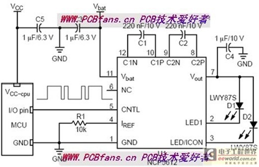
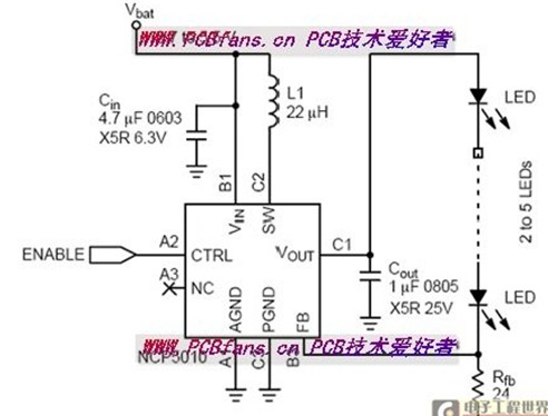
Battery-powered products need to optimize the LED driver circuit architecture that handles multiple challenges such as space constraints, high energy efficiency, and battery voltage variations—either higher or lower than the LED forward voltage. There are two common topologies: LEDs are connected in parallel with a charge pump architecture/constant current source architecture and LEDs are connected in series with an inductor boost architecture. Both solutions need to consider trade-offs. For example, the boost architecture can ensure that all LEDs flow in the same current but require inductors for energy conversion. The charge pump architecture uses small capacitors for energy conversion, but all LEDs are arranged in parallel. Too tight so that current matching becomes a tricky problem for balanced backlighting. Figure 1 shows an example of these two architectures.
PCBfans.cn tips please see the picture below:
PCBfans.cn tips please see the picture below:
Figure 1: Circuit diagram of charge pump and inductor LED driver
The following points should be made during design
1. Evaluate the approximate usage time of the display
When selecting a white LED driver, you need to consider the frequency of use of the display. If the display is backlit for a long time, having a high-efficiency converter is critical to battery life. Larger displays require more LEDs, while longer display applications benefit from more energy efficient boost topologies. Conversely, if the display is only used for short-time backlighting, efficiency may not be a critical design parameter.
2. Carefully consider LED options
LED technology continues to improve rapidly, and manufacturers are using new materials, manufacturing techniques, and LED designs to deliver more light output for the same amount of current, so that four LEDs needed for backlighting a few years ago may now use two LEDs can achieve the same backlight brightness. Not only that, but cold-cathode fluorescent lamps (CCFLs) used to backlight large 4 to 7-inch displays, and are now turning to LEDs for backlighting. In addition, the LED forward voltage is tending to be lower. Therefore, it is not only necessary to consider the driver efficiency on the driver manufacturer's data sheet curve, but also to evaluate the driver based on the selected LED. Table 1 lists some of the important specifications for several LEDs, showing the difference in forward voltage and brightness of these LEDs. It should be noted that the forward voltage range varies greatly, which means that the driver efficiency should be evaluated using the LED specification limits.
3. Pay attention to wiring
Even if each LED is driven with a very low current of 10 to 20 mA, the peak current flowing through the converter is significantly higher. This is true for inductive topologies because the peak switching current may be 10 to 20 times the average LED current. Therefore, it is necessary to use a suitable low loss wiring technique. For charge pump type topologies, the capacitor should be placed adjacent to the driver to minimize loop area to avoid radiated switching noise. For an inductive boost converter, the input and output capacitors and the inductor are placed adjacent to the driver. In addition, the current setting resistor (Rfb) should be connected directly to the chip ground because the error between the internal reference and the sense voltage directly affects the LED current accuracy.
4. Test your test product in a real environment
Consider the display's performance under high ambient light conditions and ensure that the software dimming control has sufficient dynamic range to adequately dim the display in the desired lighting environment.
Should pay attention to avoid the following problems
1. Forgot to consider the boundary and failure mode
Errors always occur. If the LED is open or shorted to ground, how should the driver handle this problem? For an inductive boost driver, if the LED string is open, the output will surge because the constant current charges the output capacitor, which requires Overvoltage protection, but this feature may or may not be integrated into the drive. This can be a problem in factory testing because the display may not have been installed during certain test steps. In addition, it is important to evaluate the surge conditions when the product is turned on, as a large amount of current consumption may reduce the battery voltage below the minimum operating threshold. This problem can be minimized by using soft start and/or software sequencing of different circuit modules.
2. Only stare at peak efficiency
Since the user can adjust the brightness of the backlight, it is important to consider that the display backlight is expected to be efficient for most of the working time. When evaluating drive efficiency, you need to consider the LED's expected operating conditions, battery voltage range, and forward voltage variation. Inductive drivers have better peak efficiency and greater tolerance for input and output voltage variations.
3. Ignore external component selection
In all design cases, low equivalent series resistance (ESR) X5R or X7R ceramic capacitors should be considered to minimize losses. Also in the inductive case, (if there is an external) Schottky rectifier forward voltage drop and inductor ESR will affect efficiency. For example, using a 0.3Ω ESR inductor to drive five series LEDs at 20mA will be 5% more efficient than a 1.3Ω ESR inductor. Of course, this is not without cost, because the lower the inductance ESR, the larger the size corresponding to the same inductance value. Fortunately, there are many new small-sized inductors that allow LED drivers to be placed under the display.
IEEE 1394/Firewire Connector Overview
The IEEE 1394 Connector series is capable of accommodating data rates up to 400 megabytes per second for serial transmission-consists of six-position connectors (for connections of computers to peripherals), and four-position connectors (for connections of digital AV equipment. We offer a screw thread size of M1.6 and two types of headers: dual inline package (DIP) and surface-mount technology (SMT). These four-position connectors help us manage a wide range of device designs and are suitable for DVD, set-top box, etc. The cable assemblies are also available with four-position to four-position type, for connection of AV equipment; four-positions to six-positions of transition type, for connections of PC and AV equipment; and six-position to six-position type for connections of PC and peripherals.
Ieee 1394 Connectors Product Features
Conforms to IEEE 1394 standard
Easy connections for plug and play devices
Available for wide range of connectors
DIP and SMT types available for PCB side
For 0.8mm and 1.6mm PC boards, M1.6 and M2.1 (4-position) panel mounting screw thread sizes
Use for automatic mounting machines with embossed tapes (4-position)
Fire Wire (IEEE 1394) Connector Wire to Borad Connectors
No of Contacts 4, 6, 9
Type
4pin IEEE 1394 Connector Female PCB Mounting Straight
4pin IEEE 1394 Connector Female PCB Mounting Right Angle
6pin IEEE 1394 Connector Female PCB Mounting Straight
6pin IEEE 1394 Connector Female PCB Mounting Right Angle
4pin IEEE 1394 Connector Male Wire Moulding type
6pin IEEE 1394 Connector Male Wire Moulding type
9pin IEEE 1394 Connector Male Wire Moulding type
9pin IEEE 1394 Connector Female PCB Mounting Right Angle
IEEE 1394 Connector With Female SMT 04P
IEEE 1394 Connector With Female SMT 09P
")
IEEE 1394 Connector Application:
IEEE1394 (Firewire) interface, IEEE1394 is a serial standard. .Like USB, IEEE1394 also support hotplug peripherals and can provide power for peripherals,
eliminating the need for built-in power supply. IEEE1394 supports multiple devices as well as synchronous data transmission.
Cameras
Camcorders
Scanners
Printers
DVD Players
Set-Top Boxes
Computer Monitors
Audio Video Receivers
Hard Drives
Audio Recording Devices
1394 Connector,Ieee 1394 Connectors,1394 Usb Connector,1394 Pcb Connector,Firewire Connector,IEEE 1394 USB Connector,1394 Firewire Connector
ShenZhen Antenk Electronics Co,Ltd , https://www.antenk.com