Sometimes it is necessary to split a single power supply into two or more parts that are not necessarily equal. This is often the case when using 6V, 12V, 15V, 24V, 36V or 48V power supplies from dry batteries or car batteries. Although there are accurate professional voltage dividers on the market, they are not necessarily available or too expensive for some projects. And sometimes ICs designed to be used as voltage dividers do not provide the required current or power.
Fortunately, for many applications, when we need a voltage divider, we can use a low-cost audio power amplifier (PAA) (such as LM386, LM380, LM384, TBA820M, TDA2002, TDA2003, TDA2030, TDA2040, TDA2050, LM1875). Etc.) Split the power supply. This power split scheme is particularly suitable for use with test and test systems.
We can build a simple, low-cost, non-switching voltage divider for the power supply of an electronic device around an audio power amplifier. The audio power amplifiers listed above, as well as many other devices, are purchased in large quantities in many projects, making them less expensive to use and replace, and less burdensome.
Audio power amplifiers are products that many manufacturers have produced for many years, so they are very popular, and the internal circuits are also open, which is very convenient to test. These ICs are easy to replace after damage.
Each of the circuits mentioned in this article is operational, but has some special features, so proper evaluation should be performed before using this circuit. The circuits described in this article are very simple and do not require complicated redesigns or adjustments to work correctly.
Three types of voltage dividers
There are generally three voltage dividers. The block diagram of these three voltage dividers is shown in Figure 1.
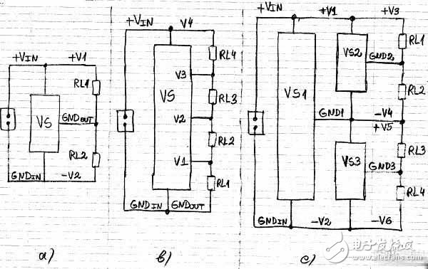
Figure 1: Common block diagram of the three main types of voltage dividers. a) a voltage divider with two outputs; b) a voltage divider with 4 outputs; c) a voltage divider with three virtual grounds.
Figure 1a shows the most common version of the voltage divider. The input voltage between +Vin and GNDin is split into two parts that do not have to be equal. The voltages of these two parts can be fixed or adjusted within a certain range. There is usually a slight difference between the input and output voltages, which is related to the implementation of a specific voltage divider.
The two output voltages are the voltage between +V1 and GNDout and between -V2 and GNDout. In this voltage divider, there is no isolation between the input and output voltages, and there is no direct connection between the input ground GNDin and the output ground GNDout (sometimes referred to as virtual ground).
Figure 1b shows a block diagram of a second voltage divider. The input voltage between +Vin and GNDin is split into 4 non-equal parts. The voltage of these parts can be fixed or adjusted within a certain range. In this case, the input ground GNDin and the output ground GNDout are directly connected. This application can be referred to as a multi-output linear regulator.
However, it should be noted that because in this voltage divider, the outputs V1, V2 and V3 can be driven by a push-pull circuit instead of a single output buffer. This is different from linear regulators because each output of the linear regulator (the output is not a push-pull circuit) usually has one transistor.
Figure 1c shows a third voltage divider. The input voltage between +Vin and GNDin is divided into four parts that do not have to be equal. In fact, this application has three voltage dividers, each splitting its input voltage into two parts. Each output ground (GND1, GND2, and GND3) is driven by a push-pull circuit.
We should pay attention to the way the voltage divider output voltage is measured. In this example, V1 and -V2 are measured for GND1, V3 and -V4 are measured for GND2, and V5 and -V6 are measured for GND3.
We mainly use a voltage divider based on the block diagram circuit shown in Figure 1a, and the voltage divider based on Figure 1b is rarely used.
Advantages of analog voltage divider based on audio amplifier
Modern industry has many types of switching DC/DC converters that can be used as a voltage divider. However, these devices are not always available for long periods of time, the price may not be affordable, they may generate a lot of electromagnetic noise, or have other disadvantages.
There are many advantages to using audio power amplifiers, audio op amps (AOAs), and similar IC and audio modules as voltage dividers:
â— There are many manufacturers that produce audio power amplifiers and have been around for many years. They are available from many distributors, they are already very popular, and they are low in price.
â—The audio power amplifier is easy to test and needs to be replaced easily.
• Audio power amplifiers have very low noise both in and out of the audio range. They do not generate a lot of output noise, radio frequency waves or electromagnetic interference (EMI)
â—Many audio power amplifiers have internal thermal protection, overcurrent protection, and in some cases reactive load protection and overvoltage protection
â— Many audio power amplifiers can be easily mounted on additional heat sinks when needed
Just to illustrate, before we consider an amplifier-based voltage divider, let's take a look at a variety of useful voltage dividers based on diodes and transistors.
Diode and Zener diode based voltage divider
We may need to obtain several milliamps of current from two or more low-voltage power supplies or voltage sources derived from ordinary DC power supplies, and the power management of such circuits does not need to be very strict. In these cases, we can use voltage dividers based on diodes, Zener diodes, and shunt regulators.
Modern industry offers a wide variety of Zener diodes with power consumption between 0.3W and 1.3W and a reference voltage tolerance of ±2% or better. These Zener diodes can be used to implement certain types of voltage dividers. Figure 2 shows three examples.
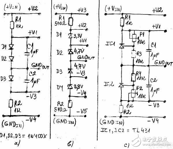
Figure 2: Voltage divider using diodes and Zener diodes. a) a voltage divider using a diode; b) a voltage divider using a Zener diode; c) a voltage divider using two shunt regulators (TL431).
Figure 2a shows a simple voltage divider using a diode. We can connect any suitable number of diodes or light-emitting diodes (LEDs) in series, which will act as shunt or shunt regulators. In this example, two diodes D1 and D2 produce a positive output voltage +V1, and another diode D3 produces a negative output voltage -V3. The output ground GNDout can be at any point between the diodes.
Figure 2b shows a simple voltage divider using a Zener diode. We can connect any suitable number of Zener diodes in series and they will be used as shunt or shunt regulators. In this example, two diodes D1 and D2 produce positive output voltages +V1 and +V2, and the other two diodes D3 and D4 produce negative output voltages -V3 and -V4. The output ground GNDout can be at any point between the Zener diodes. In this example GNDout is between D2 and D3. Zener diodes can be of the same or different types.
Instead of diodes and Zener diodes, we can use a shunt regulator like the TL431. The advantage of this solution is that we can adjust the output voltage by selecting resistors, or trimming potentiometers or other components.
Figure 2c shows a simple voltage divider using a TL431 adjustable shunt regulator. In this example, we use two TL431 or LM341 to generate a positive output voltage +V1 and a negative output voltage -V3. Voltage V1 can be adjusted with trimmer potentiometer P1, and negative output voltage -V3 can be adjusted with P2.
We can connect any suitable number of shunt regulators in series, as shown in Figure 2a and Figure 2b. In fact, these regulators can be seen as adjustable Zener diodes.
Voltage divider based on bipolar junction transistor (BJT)
The voltage divider shown in Figure 2 does not have a push-pull output circuit, so much power is wasted without load. We can avoid this problem with a voltage divider based on a bipolar junction transistor. This voltage divider is especially suitable when we need high output voltage, high current, high power or when we don't need very good output voltage regulation.
As an example we will discuss a few simple applications later. These circuits have a simple adjustment of the push-pull output circuit and output voltage. They are similar to transistor type audio amplifier circuits that operate as DC amplifiers.
Figure 3 shows an example of two simple voltage dividers built around two transistors.
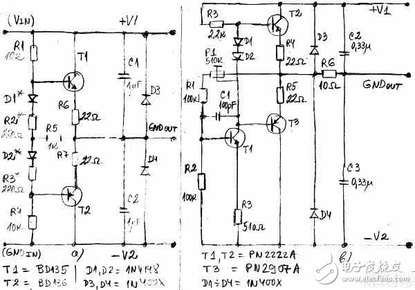
Figure 3: A simple voltage divider built with transistors.
Transistors T1 and T2 in Figure 3a are used to buffer the voltage divider output voltages constructed by resistors R1 through R4 and diodes D1 and D2. Diodes D1 and D2 function as temperature compensation, but are not required. If these two diodes are used, D1 should be in thermal contact with T1 and D2 should be in thermal contact with T2. If D1 and D2 are not used, then the R2 and R3 values ​​are increased accordingly.
Resistors R5, R6, and R7 provide simple local feedback that can be used to improve and protect the circuit. R5 is much larger than R6 and R7. The component value calculations in the circuit are similar to the component value calculations in the emitter follower circuit.
Figure 3b uses three transistors and a more efficient output voltage regulation circuit with negative feedback. The negative feedback provided by resistor R1 and trimmer potentiometer P1 stabilizes the output voltage. The output voltages +V1 and -V2 are set by P1, R1 and R2. D1 and D2 are used for temperature compensation. Resistors R4 and R5 provide local negative feedback and protect output transistors T2 and T3 to some extent.
Sometimes we need to adjust and more effectively adjust the output voltage produced by the voltage divider. In this case, we can solve these problems using a typical differential amplifier built with transistors. Figure 4 shows a voltage divider built on the basis of the five transistors T1 to T5.
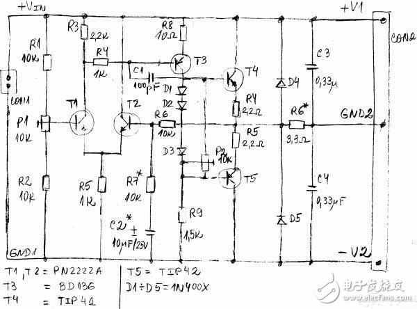
Figure 4: Voltage divider designed on the basis of a differential amplifier built into a transistor.
T1 and T2 are used as differential amplifiers. T3 is an amplifier and driver for output transistors T4 and T5. Resistor R6 provides negative feedback for stabilizing the output voltage. R7* and C2* are not required. C1 is necessary because it provides frequency compensation for the circuit.
The output voltages +V1 and -V2 are set by R1, R2 and P1. Diodes D1, D2, and D3 are used for biasing and temperature compensation of the output transistors. The trimmer potentiometer P2 is used to adjust the quiescent current of the output transistor, for example from 1mA to 10mA, depending on the load. Resistors R4 and R5 provide local negative feedback and provide a degree of protection to output transistors T4 and T5.
Voltage divider using op amp and bipolar junction transistors
If the load is variable or not symmetrical, the voltage dividers shown in Figures 3 and 4 may not work well. In order to solve this problem, sometimes we will use a voltage divider based on a single op amp (such as TL071, OPA134, NE5534/A or LM741) and additional complementary bipolar junction transistors (such as PN2222A+PN2907A, BD135+BD136, etc.). . Figure 5 shows an example of such a voltage divider.
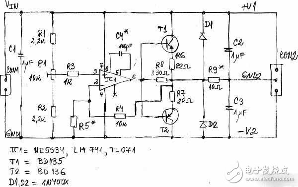
Figure 5: A simple voltage divider designed with op amps and bipolar junction transistors.
The output voltage is regulated with P1. This voltage divider works like a DC amplifier with a gain Av equal to Av = 1 + R4 / R5. R5 can be omitted if it is not needed, and the gain at this time is unit 1. This circuit can also be used as a follower and current buffer.
The output current of the voltage divider is limited to 50mA to 2000mA, depending on the output capabilities of transistors T1 and T2 and the op amp. Capacitor C4* is only used when external frequency compensation is required for the op amp. Most audio power amplifiers include all of the components shown in Figure 5, making them ideal for building adjustable and non-adjustable voltage dividers.
The Led Emergency Inverter is a combination of a white high-quality ABS shell and an external lithium ion battery , which is small in size and easier to hide in the ceiling . This Emergency Conversion Kit is suitable for all external driver of LED lights in the wide voltage AC85-265V range , equipped with lithium ion battery that can be recharged up to 500 times , the emergency power supply has multiple protection functions , such as overcharge , over-discharge , short circuit protection , etc .

Led Inverter,Led Power Converter,Led Emergency Battery Driver,Emergency Light Conversion Kit
Jiangmen City Pengjiang District Qihui Lighting Electrical Appliances Co., Ltd , https://www.qihuilights.com