Author: Alan Rankin, Texas Instruments DLP® Products division business development manager; Jason Thompson, Texas Instruments DLP® Products Division Applications Engineering Manager

On February 7, 2015, at the 87th Science and Technology Awards Ceremony of the Academy of Motion Picture Arts and Sciences, Dr. Larry Hornbeck, inventor of Texas Instruments' DLP® chip, won the Academy Award®. The DLP chipset has fundamentally changed the way film production, distribution and viewing, and now more than 80% of cinemas worldwide use this chipset.
Similar to the impact of DLP technology on the film industry, this technology is now preparing to revolutionize the automotive industry through applications such as new displays and automotive lighting.

(Table 1)
  
The development momentum of HUD2.0
Existing head-up display (HUD) systems often only display redundant information, ie information that is available elsewhere in the vehicle. And the new generation of this technology, HUD2.0, can display Advanced Driver Assistance System (ADAS) information. In addition to on-board sensors, cameras and vehicle-to-vehicle/infrastructure communication (V2X), the amount of information around the vehicle is also exponentially increasing. The challenge we face is how to effectively communicate what important information is “known†to the vehicle and pass it on to the driver, but only when we migrate to semi-autonomous and autonomous driving functions will this information increase.
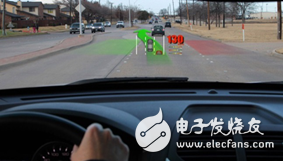
Figure 1 Orthographic projection of AR HUD
HUD 2.0 will convey this information in a natural and intuitive way, enhancing the driver's global fixed view and displaying the vehicle's known information in a positive projection. The navigation indicator, lane departure warning (LDW) and adaptive cruise control (ACC) indicator functions are displayed from the driver's perspective at a natural image distance. As shown in Figure 1, this figure shows how to 'enhance' the reality of the driver's view and provide useful information in real time. Here we can, the image is displayed in bright, lifelike colors, and superimposed on the object at a natural distance, so the driver can easily use the information with minimal interference.
Furthermore, unlike existing HUDs used as "auxiliary" display systems in the user interface paradigm, HUD 2.0 is located at the center of the Human Machine Interface (HMI) strategy and will serve as the primary information display system. Similarly, the new generation of HUDs also expects excellent image quality and consistent readability under different daylight conditions.

Figure 2 FOV and VID affect the perceived HUD graphics size
Challenge
HUD 2.0 requires many new aspects to be gained from traditional HUD designs. Although the detailed description of the HUD design is beyond the scope of this article, it is still necessary to review some key parameters.
As shown in Figure 2, the field of view (FOV) and virtual image distance (VID) play an important role in determining the perceived image size. While the traditional HUD field of view covers only one lane, the HUD 2.0, which has a larger field of view and a longer virtual image distance, allows the driver to see images that are more than one lane of traffic. These enhancements in field of view and virtual image distance require higher brightness, more saturated colors, higher efficacy, and greater daylight tolerance. In addition, these new parameters need to be met while meeting the environmental conditions of all traditional vehicles. Table 2 below lists some of the parameters of HUD 2.0, compared to traditional HUD systems.

Table 2 Comparison of key parameters of the new generation HUD2.0 with the key parameters of traditional HUD
Brightness and efficacy
A larger field of view and a higher brightness level provide the driver with an easy to view image. To ensure readability under various lighting conditions, the HUD should be able to generate a virtual image between the specified 15,000 cd/m2 and 30,000 cd/m2. However, the absolute power required to create this image should be kept low, which not only minimizes the capacity required for thermal management, but also maintains luminous flux over a viable source of light (LED). In order to increase the field of view and increase the brightness without increasing power consumption, a more efficient imager is necessary. Texas Instruments DLP 0.3†WVGA class A100 digital micromirror device (DMD) is more than 66% efficient, significantly improving system efficiency to meet the above parameters. With efficiency improvements, HUD systems based on DLP technology and RGB LEDs can achieve Brightness and wide field of view. For example, a system designed with .3†WVGA DMD and OSRAM Q8WP RGB LED[2] can achieve more than 15,000 cd/m2 brightness with a 10 degree field of view using only 6.0 W of LED power, even The power of the auxiliary HUD system is smaller than the current one. The system has a power of 10.6 lm/W (the lumens per watt).
Color saturation
Many traditional TFT/LCD HUD designs use white LEDs that produce red, green, and blue through the filter. In contrast, HUD systems based on DLP technology use red, green and blue LEDs to provide more saturated colors, which enhances the readability of images on HUD displays [3]. Some key performance indicators can be used to determine the color performance of the system, including comparing the hue of each color defined by the color gamut, dominant wavelength, and color saturation measured by its color gamut and NTSC color gamut.
Table 3 compares the TFT/LCD white LED architecture [1] with the HUD architecture using RGB LEDs based on DLP technology. Compared to NTSC, the RGB LED has a larger color gamut and deeper red and blue saturation.
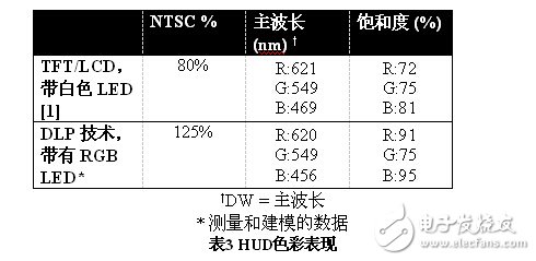
Table 3 HUD color performance
Daylight heat load
With the expansion of the HUD system's field of view, the solar energy collected by HUD optical instruments has also increased. In addition, as the virtual image distance increases, the driver can view the image at a normal angle compared to the real world fixed view, and the solar energy is more focused onto the HUD's internal imager. The effect of collecting more sunlight and focusing this ability into smaller spots of internal imaging can be damaging. The HUD system based on DLP technology creates an internal image of the HUD system using diffuse screen material. For conventional HUD systems, an imager (typically a TFT panel) directly emits a HUD image.
The diffuse screen is a passive component that has two main advantages: 1) it does not absorb solar energy – it diffuses light 2) it is not itself a heat source. With these attributes, the DLP-based HUD system is easier to extend to the large field of view and longer virtual image distances required for augmented reality HUD systems.
Polarized sunglasses
In addition to the brightness that is sufficient to be seen under various ambient light conditions, the HUD virtual image is also readable when the driver wears polarized sunglasses. Since DLP technology is projected as non-polarized, this enables OEMs to optimize the HUD used for polarized sunglasses.
Environmental conditions
The imaging technology used in automotive HUD systems must be able to operate reliably under harsh environmental conditions, such as high humidity, extreme temperature changes, shock and vibration. DMD is a micro-electromechanical system that is amazing for its ability to experience the temperature cycling, shock and vibration experienced in cars. The DLP 0.3†WVGA class A100 DMD meets these conditions. When the mirror resonant frequency is much higher than 100 kHz, its mechanical structure is rugged under the shock and vibration of the 5 kHz range. Table 4 lists the .3. "WVGA class A100 DMD successfully completed some key tests.

in conclusion
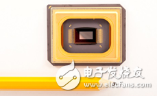
With the increasing popularity of ADAS technology in automobiles, HUD is becoming increasingly important for vehicle HMI strategies. As HUDs transition from small auxiliary displays to large main displays, expectations for image quality, readability and reliability are increasing. DLP technology has been widely used in consumer electronics and commercial applications for nearly two decades, laying a solid foundation for automotive-grade chips. As shown in Figure 3, the DLP 0.3†WVGA class A100 DMD specifically meets the environmental requirements of the new generation of automotive HUDs.
Reference material
[1] E. Buckley, “Pixtronix DMS(tm) technology for head-up displays,†in SID Vehicles and Interfaces Conference, Dearborn, MI, 2011.
[2] OSRAM Opto Semiconductor. [Online]. Available: http://
[3] KIRSD a. BE Blankenbach, “Comparison of the Readability of Colour Head-up Displays Using LED and Laser Light Sources,†in SID, Symposium Digest of Technical Papers, 2010.
Anti-virus disposable safety coverall Protective Clothing
This product is non-sterile
It can be used in hospital, just hospital staff need to do sterilization before using;
It can effectively resist the penetration of bacteria, viruses, alcohol, blood, body fluids, air dust particles, can effectively
protect wearer from the theat of infection.
Protective Clothing
Protective Work Clothing,Ebola Protective Clothing,Safety Protective Clothing,Disposable Protective Clothing
Guangzhou HangDeng Tech Co. Ltd , https://www.hangdengtech.com