The IEEE 1588 standard was born in 2002 and mainly defines the synchronization protocol for network distributed clocks. This clock synchronization method has been the first choice for many different applications, such as test and measurement, telecom and multimedia stream processing. This standardized clock synchronization method is cost-effective, supports heterogeneous systems, and provides nanosecond synchronization accuracy.
This article describes the improvements in the original IEEE 1588-2002 standard and the updated version of IEEE 1588-2008. As IEEE 1588 becomes more and more important in some target applications, dedicated hardware is also integrated into the ADSP-BF5181 Blackfin® embedded processor to support IEEE 1588. This article provides an overview of its capabilities and, through an example, shows the clock synchronization performance results obtained with the ADSP-BF518 processor solution.
what time is it now?
Most systems need to use the local oscillator to maintain their own time concept. Figure 1 shows how hardware and software can be combined to generate time information within the system.
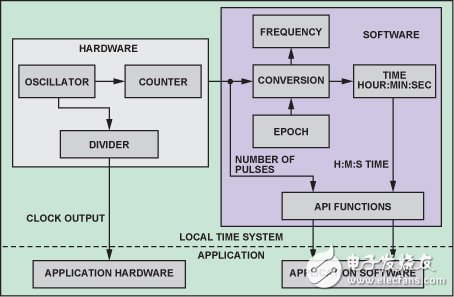
Figure 1. Local timing
This time information is available to both hardware and software resources within the system. For hardware, the oscillator clock generates one or more physical clock signals (clock outputs) that can be used to drive or trigger other parts of the system. The time maintained in the software is often referred to as "system time." The system time can be expressed in the form of clock pulses or seconds/nanoseconds. The system software uses the oscillator clock pulse number and its frequency information to derive time and provides an Application Programming Interface (API) function that other parts of the software can use to retrieve and set the time. If an absolute time is required, the time provided will be associated with a predefined point in time, the base time point.
Clock synchronizationMany applications require two separate devices to work in a synchronized manner. If each device relies solely on its own oscillator, the difference in characteristics and operating conditions of each oscillator will limit the ability of the clock to operate synchronously. Some simple and workable solutions can overcome these limitations, including:
All devices share a single physical oscillator. This method is only for distances that are very close
All devices use oscillators with nearly identical characteristics. This approach is not feasible because it is difficult to get an almost identical oscillator and to ensure that performance does not drift over time. More importantly, the operating conditions of the oscillators are not the same.
If all devices are interconnected via a communication network (such as Ethernet), these devices can exchange time messages over the network to dynamically adjust their clocks based on a single "master" clock. Using the traditional time synchronization protocol, Network Time Protocol (NTP), each device in the system adjusts its clock based on the time information it gets from the NTP time server. However, this protocol can only achieve millisecond synchronization accuracy.
IEEE 1588 defines a new protocol that enables nanosecond synchronization accuracy. The following discusses how this standard implements this level of clock synchronization.
What is the role of IEEE 1588?The IEEE 1588 standard defines a time synchronization protocol for devices that are geographically dispersed but interconnected by some communication technology, such as Ethernet. The device maintains the same absolute system time (in seconds and nanoseconds) by exchanging timing messages.
An intuitive way to achieve this is to designate a device with the "best" (most accurate) clock as the "master clock" device and let it broadcast its time to other devices. Other devices will adjust their respective time to match the time sent by the master clock. However, this solution also has several shortcomings:
1. The master clock device cannot broadcast time at very short intervals, so the "slave" clock device must use its own separate "poor" oscillator on the master clock device.
2. There is inevitably a delay in the broadcast path, which depends on the communication technology, such as the time it takes for a physical signal to travel from one device to another along a wire. This delay will further increase the loss between the master clock and each slave clock.
3. There is a difference in the broadcast path between the master clock device and each slave clock device, which further reduces the synchronization accuracy between the slave clock devices.
IEEE 1588 requires solving the second and third problems by measuring path delays. It also requires that the slave clock to be adjusted keeps pace with the master clock, thereby alleviating the first problem. If possible, use a smaller broadcast interval and a higher quality oscillator to further alleviate the first problem
How IEEE 1588 measures communication delayIEEE 1588-20022 defines four messages, Sync, Followup, DelayReq, and DelayResp, to measure the communication delay between the forward (primary to slave) and backward (slave to master) paths. The updated version of IEEE 1588-2008, 3 also provides other mechanisms for adding three types of messages, PdelayReq, PdelayResp, and PdelayRespFollowup, to measure "point-to-point delay."
Among these messages, Sync, DelayReq, PdelayReq, and PdelayResp are so-called "event" messages that must be "time stamped" (record local time) when leaving and arriving on a device. There are two ways to timestamp a packet.
1. The software timestamp appears when the message is processed by the software. This usually occurs in the Receive/Send Interrupt Service Routine (ISR) of the message, which is the current value of the system time.
2. A hardware timestamp appears when the message actually arrives or leaves the device. This timestamp operation is performed by hardware and the hardware maintains its own continuous time information.
Both timestamp methods are accepted by IEEE 1588, but the hardware timestamps are significantly more accurate, as described below.
Delay from master clock device to slave clock device
The messages Sync and Followup are sent by the master clock device, which is responsible for receiving these messages and calculating the communication path delay from the master clock device to the slave clock device.
In Figure 2, at time point Tm1, the master clock device software reads the current local system time (Tm1, software timestamp), inserts it into the Sync message, and sends the message. The message leaves the master clock device at a later time point Tm1', which is the hardware timestamp. The message arrives at the slave clock hardware at time point Ts1' (from the clock device local time), which is received by the slave clock device software at a later time point Ts1. The software will read the hardware timestamp to get Ts1'. If there is no communication delay, Ts1' should be equal to (Tm1' + Tms), where Tms is the time difference between the master clock and the slave clock. The ultimate goal of the agreement is to compensate for this time difference.
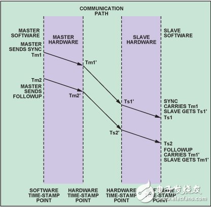
Figure 2. Measuring the communication delay between the master clock device and the slave clock device
After sending the Sync message, the master clock device software reads the departure time Tm1' of the Sync message through the timestamp unit, inserts it into the Followup message, and then sends the message at time Tm2. This message was received from the clock device software at time Ts2. At this point, the slave clock device software has two times: Ts1' (Sync arrival time) and Tm1' (Sync departure time). The master-slave path delay Tmsd is determined by Equation 1.
 (1)
(1)
Delay from clock device to master clock device
The DelayReq message is sent from the clock device, and the master clock device responds by sending a DelayResp message. With these messages, the slave clock device can calculate the communication path delay from the clock device to the master clock device.
At time point Ts3 (Fig. 3), the current local system time (T s3) is read from the clock device software, inserted into the DelayReq message, and the message is sent. After sending the message, the timestamp is read from the clock device software to obtain the message leaving time Ts3' and wait for a response from the master clock device.
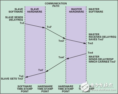
Figure 3. Measurement delay from primary communication
The DelayReq message arrives at the master clock device at a later time point Tm3' and is processed by the master clock device software at time point Tm3. The software then reads the timestamp to get the arrival time Tm3', inserts it into the DelayResp message, and sends it to the slave clock device at time point Tm4. When the DelayResp message is received from the clock device software at time point Ts4, it can extract the time Tm3' and calculate the delay Tsmd from the primary communication by Equation 2.
 (2)
(2)
There is an unknown variable in Equation 1 and Equation 2, that is, the master-slave time difference Tms, so Tmsd or Tsmd cannot be obtained separately. However, if we reasonably assume that the communication path is symmetrical, ie
 (3)
(3)
- This is the key assumption for the establishment of IEEE 1588 - then, add Equation 1 and Equation 2 to get
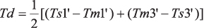 (4)
(4)
Since these slave clock devices seek to synchronize with the master clock device, all of these calculations are performed by these devices. The slave clock device obtains Tm1' from the Followup message of the master clock device, obtains Ts1' from its Rx (receive) timestamp, obtains Ts3' from its Tx (send) timestamp, and obtains Tm3' from the DelayResp message of the master clock device.
How to calculate the time difference between the slave clock and the master clock
Once the communication path delay Td is obtained, the time difference between the slave clock and the master clock can be easily calculated using Equation 1 or Equation 2, as shown in Equation 5 and Equation 6.
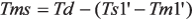
(5)
(6)
How to adjust the time from the clock deviceAfter knowing the time difference from the master clock, each slave clock needs to adjust its local time to be consistent with the master clock. This task includes two aspects. First, the slave clock device needs to add a time difference to adjust the absolute time so that its time is exactly the same as the master clock time. Second, the slave clock device needs to adjust its own clock frequency to be consistent with the frequency of the master clock. We can't rely on absolute time alone, because the time difference is only applied within a certain period of time, it may be positive or negative; the result of the adjustment is to jump forward or backward from the clock time. Therefore, in actual operation, the adjustment is performed in two steps:
1. If the time difference is too large, for example, 1 second or longer, the absolute time adjustment is applied.
2. If the time difference is small, change the frequency of the slave clock by a certain percentage.
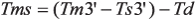
In general, the system becomes a control loop where the master clock time is the reference command and the slave clock time is the output that tracks the master clock time, the difference between the two driving the adjustable clock. PID control can be used to achieve specific tracking performance, which is a common approach in many IEEE 1588 implementations. Figure 4 shows this control loop.
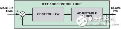
Figure 4. IEEE 1588 Control Loop.
Point-to-point delayThe revised IEEE 1588-2008 introduces a new mechanism to measure path delays, called point-to-point (P2P) delays. In contrast, the master-slave mechanism discussed above is “end-to-end†(E2E) latency. In a network supporting IEEE 1588-2008, the master clock device can be directly connected to the slave clock device or connected to several relay stations (levels). The E2E delay is actually the "total" delay from the master clock device to the slave clock device, including all relay stations in between. However, P2P latency is limited to two directly connected devices. The total delay of the communication path is equal to the sum of the P2P delays of all relay stations. From the perspective of ensuring path symmetry, the P2P mechanism provides higher accuracy.
As mentioned above, IEEE 1588-2008 adds three messages, PdelayReq, PdelayResp, and PdelayRespFollowup, to measure P2P latency. These messages work in a similar manner as described above, see Reference 3 for details.
Factors affecting synchronization performanceWell-designed IEEE 1588 devices enable highly accurate clock synchronization, but you must also understand the main factors that directly affect synchronization performance, including:
1. Path Delay: As mentioned above, the path delay measurement of IEEE 1588 assumes that the communication path delay is symmetric, that is, the forward path has the same transmission delay as the backward transmission delay. In addition, the delay should not change during the delay measurement. Delay variations during measurement can cause asymmetry and delay jitter, which directly affects synchronization accuracy. Although delay symmetry and jitter cannot be controlled outside the boundaries of IEEE 1588 devices, path symmetry and jitter can be improved within the device if the measurements are based on hardware timestamps. Software timestamps cause significant jitter due to interrupt latency, context switching, and thread scheduling, while hardware timestamps are not
2. Clock drift and jitter characteristics: The frequency and phase of the master clock represent the input of the tracking control system, and the slave clock is the control object. Any time-varying behavior of the master clock can disturb the control system, resulting in both steady state and transient errors. because
3. Control Law: How to adjust the time error of the slave clock device from the clock adjustment depends on the control method. Control law parameters include settling time, overshoot and steady state
4. Clock resolution: As shown in Figure 1, the resolution of local time is determined by the clock frequency; the minimum time increment is one cycle of the clock signal. IEEE 1588-2002 supports a time resolution of 1 ns, and IEEE 1588-2008 supports a time resolution of 2 -16 ns. A clock of 2 16 (!) GHz (or even 1 GHz) is unrealistic. The quantification of the local clock affects the precision of local time measurement and control
5. Sync message transmission cycle: The update frequency of the slave clock will eventually affect the synchronization accuracy. Because the time error is the overall cumulative value of the clock frequency error, the longer the transmission period, the time error observed by the next Sync will generally
6. Delayed Measurement Frequency: Delay measurements are performed periodically at intervals that do not significantly change the delay between adjacent sample points. If the delay of the IEEE 1588 network varies greatly, increasing the delay measurement frequency can improve the clock synchronization performance.
Which is the main clock?After considering how to accurately determine the time difference between the master clock device and the slave clock device, the next related question is how to determine which device acts as the master clock in hundreds of interconnected devices.
IEEE 1588 defines a method called the "Best Master Clock" (BMC) algorithm for selecting a master clock device. This approach requires each device of the IEEE 1588 network to provide a data set describing the nature, quality, stability, unique identifier, and preferred settings of its local clock. When a device joins an IEEE 1588 network, it broadcasts the data set of its clock and receives the data set of all other devices. Using the data set of all participating devices, each device runs the same BMC algorithm to determine the primary clock and its own future state (master clock or slave clock). Since all devices use the same data to execute the same algorithm independently, the conclusion will be the same and no negotiation is required between devices. See references 2 and 3 for more details on the BMC algorithm.
ADSP-BF51 8 processor supports IEEE 1588
A new addition to the Analog Devices Black fi n DSP family: the ADSP-BF518 processor. Like the previous product ADSP-BF537, 4 the processor has an Ethernet Media Access Controller (EMAC) module built in. It also has a TSYNC module that further extends the capabilities of the IEEE 1588 standard EMAC feature; it also provides additional features to support various IEEE 1588 applications for Ethernet. Figure 5 shows a block diagram of the TSYNC module. ADSP-BF51x Blackfin Processor Hardware Reference provides more information 5
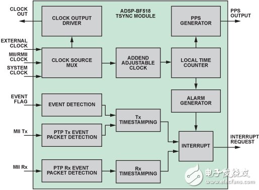
Figure 5. Block diagram of the ASYNC-BF518 processor TSYNC module.
Packet detectionThe ADSP-BF518 processor can detect all event messages for IEEE 1588, including incoming and outgoing packets, and provide hardware timestamps. Because the accuracy of the event message timestamp and its extraction location affect the symmetry and stability requirements of the path delay, the accuracy of the IEEE 1588 system is highly dependent on both. The TSYNC module of the ADSP-BF518 continuously monitors the hardware interface between the MAC controller and the Ethernet "Physical Interface Transceiver" (PHY), the "Media Independent Interface" (MII), and generates hardware whenever an event message is detected. Time stamp, this feature improves the synchronization accuracy of the ADSP-BF518.
The event message detection function is programmable and has two basic configurations: IEEE 1588-2002 (default state) or IEEE 1588-2008. In addition, this programmability also supports future versions of IEEE 1588, as well as other general protocols that require timestamps, including a timestamp configured to give each Ethernet packet to and from the processor.
Flexible clock sourceThe properties of the local clock are important to the performance of the IEEE 1588 system. To meet the requirements of a variety of different applications, the ADSP-BF518 processor offers three local clock source options: system clock, external clock or Ethernet clock. If your application has specific clocking requirements, you can select an External Clock and provide a custom clock source. If the master clock device is "back to back" connected to the slave clock device, this clock option provides good accuracy because the "Ethernet Clock" comes from the Ethernet line and both devices operate on the same clock. A general application can select the "system clock" of the processor as the clock source.
The selected source clock is also driven by the TSYNC module, which is used as a processor output via a specific pin, Clockout, which can be used by other parts of the system to provide local time information.
PPS outputThe Pulse Per Second (PPS) signal is a physical representation of the time information. It is nominally a 1-Hz signal that emits a pulse every 1 second conversion time. It can be used to control local devices or provide an auxiliary time channel in the event of a network failure. It can also be used for testing. The phase difference between the PPS signals of the two devices is the physical measure of the time offset between the two
The ADSP-BF518 processor provides flexible PPS output. It uses a programmable "start time" (PPS_ST) and period (PPS_P) to generate a signal that is pulsed at time (PPS_ST + n &TImes; PPS_P), where n = 1, 2, 3. . . . The basic usage is to set PPS_P to 1 second and set PPS_ST to any time in the future, resulting in a PPS signal. With reference to the basic usage, this PPS output function can be used to generate periodic signals with programmable frequencies and start times.
Secondary snapshotSome applications may need to follow the flag signal switching instructions to timestamp an event. The TSYNC module of the ADSP-BF518 uses a dedicated pin to receive external flags through the auxiliary “snapshot†function to implement this request. The toggle flag will trigger the module to capture the current local time in the timestamp register for software access. .
Call the policeIf the application needs to perform a task at a specific time, the "Alarm" function of the TSYNC module can be used. This feature sets the local absolute time at which a processor interrupt is triggered. The software can then use the interrupt to perform the task.
Adjustable clockThe adjustable clock of the TSYNC module is an "add-based" clock. As shown in Figure 6, it obtains a fixed input clock signal and outputs a "stealing pulse" version of the input signal: for each input clock, the value of "addend" is added to the accumulator, and each accumulator On overflow, the carry bit drives the “local time counterâ€, which produces the local time in terms of the pulse count value. Changing the addend can adjust the frequency of the local clock because the addend determines the frequency at which the accumulator overflows, thereby determining how often the local time counter is incremented. If the input clock frequency is Fin and the value of the addend is A, the local clock frequency is:
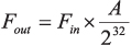
(7)
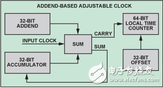
Figure 6. Adjustable clock based on addends
IEEE 1588 implementation with ADSP-BF518 processor
A complete IEEE 1588-2008 compatible system is built on the ADSP-BF518 processor, as shown in Figure 7.
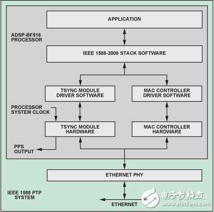
Figure 7. IEEE 1588 implementation with ADSP-BF518
The processor's TSYNC module detects incoming and outgoing IEEE 1588 messages and time stamps event messages via hardware. The IEEE 1588 protocol stack software provided by IXX AT ( IXX AT AutomaTIon GmbH) implements the message exchange protocol required by the standard. It uses the TSYNC driver to read, write, and adjust the TSYNC clock and uses the MAC controller driver to send and receive messages at the Ethernet MAC layer (the second layer of the Open Systems Interconnection model). It also implements control laws and filtering for P2P delay measurements. The Ethernet PHY selects the NaTIonal Semiconductor DP838486 with low jitter delay. For simplicity, the TSYNC module clock source selects the processor's system clock (80 MHz).
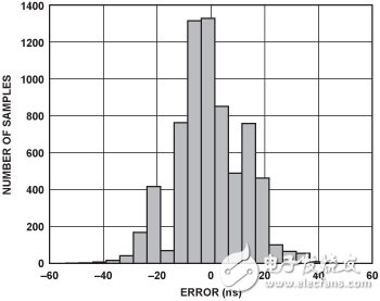
Figure 8. Slave clock error histogram of the IEEE 1588 system on the ADSP-BF518
Figure 8 is a measurement error histogram between two identical ADSP-BF518 IEEE 1588 systems, from which the clock synchronization performance of the device can be seen. A total of 6938 measurements were taken in approximately 1700 seconds. The final average error is 0.015 ns with a standard deviation of 12.96 ns. The Sync message interval used for this test is 0.25 seconds.
in conclusionThe IEEE 1588 standard provides a highly accurate, low-cost method for distributed clock synchronization. Although IEEE 1588 does not explicitly require hardware support, hardware-assisted message detection and time stamping are critical to achieving extremely high synchronization accuracy. The ADSP-BF518 provides hardware support for IEEE 1588-2002 and IEEE 1588-2008, including support for various applications. Implementing IEEE 1588 technology with the ADSP-BF518 processor and IXXAT IEEE 1588-2008 protocol software has proven to enable high-accuracy clock synchronization.
Guangzhou Yunge Tianhong Electronic Technology Co., Ltd , https://www.e-cigaretteyfactory.com