Since the introduction of the Czechoslovak writer Karel and Chapec's "Rossam Robots Universal Company" in 1920, people have been full of illusions and expectations for robots. With the continuous development of society, the division of labor in all walks of life is becoming more and more detailed, and robots can play an important role in replacing people's labor. At the same time, with the development of science and technology, robots working in dangerous places such as expeditions, disaster relief, and explosions, as well as robots used in automated production, are becoming more widespread. Therefore, the development of intelligent rescue robots has become urgently needed and necessary. The article discusses the design of intelligent rescue robots.
1 Hardware design of intelligent rescue robot
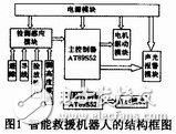
The intelligent rescue robot is mainly composed of a power module, a detection sensing module (implementing a line inspection, obstacle avoidance, coin insertion, ranging function), an acousto-optic alarm module, a controller module, a motor drive module, and a display module, and the structure thereof. The block diagram is shown in Figure 1.
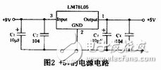
The energy of the intelligent rescue robot comes from the six-section five-cell battery at the bottom of the robot. It is powered by the traditional 7805 voltage regulator circuit to its microcontroller and peripheral sensors. The circuit is shown in Figure 2. Some sensors use a 5V low-voltage power supply to prevent the robot from detecting obstacles prematurely and stopping.
1.2 Detection Sensor Module
1.2.1 Patrol circuit
We use the infrared pair tube for the line inspection module. The infrared pair tube consists of an LED and a phototransistor that changes the positive base current based on the intensity of the light from the LED reflected back from the ground. When the pull-up resistor is connected to the base of the phototransistor, the intensity of the reflected light can be judged according to the measurement of the base voltage. The strong light indicates that the underside of the detector is white, the weak light indicates that the light below is weak, and most of the light is absorbed by the black line. . For the output analog signal, we introduce it into the five voltage comparators LM339 for processing. One input end of the voltage comparator LM339 is connected to the infrared pair tube, and the other end is connected to the sliding rheostat. The sensitivity of the infrared pair tube to the black line can be realized by adjusting the sliding rheostat. The other end of the comparator LM339 is connected to the MCU for detection after being connected to the pull-up resistor.
1.2.2 Obstacle avoidance circuit
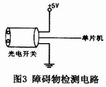
The obstacle avoidance part uses a photoelectric switch and places it in all directions that the robot needs to measure. In order to reduce the measuring distance of the robot to ensure the normal operation of the robot, we use a low-voltage 5V power supply, although the power supply voltage is slightly insufficient, but it can guarantee its normal short-distance detection. The high and low levels of the signal line of the photoelectric switch can reflect the presence or absence of obstacles in front, and the obstacle detection circuit is shown in FIG.
1.2.3 Ultrasonic distance measuring circuit
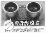
Due to the high performance of the ultrasonic wave, the slow energy consumption, and the long distance traveled in the medium. We use the DIP-ME007 ultrasonic ranging module to complete the height measurement function, and its circuit board is shown in Figure 4. The DIP-ME007 ultrasonic ranging module can quickly and conveniently measure the distance between the bottom of the bridge and the distance measuring module. This module has five pins VCC, tring, echo, out, GND. The output of the DIP-ME007 ultrasonic ranging module is pwm mode. After VCC and GND are connected, send a high level of more than 10 s to the tring, and then wait for the high level output at the receiving port echo. The MCU uses the edge of the edge to trigger, and then starts timing after the trigger. When the level becomes low, the timer is started, and the value at this time is the time taken for the ranging. The measured distance is obtained from S=Ct/2. Mobile ranging can be achieved by such periodic measurements. The MCU automatically saves the measured data and compares it with the previous ranging result. The maximum value is retained. When the data is not measured more than the previous time for five consecutive times, the detection is stopped and the maximum value is recorded. When the black line is detected again, the bridge has been successfully bridged, and the MCU control display module displays the measured maximum value on the LCD screen.
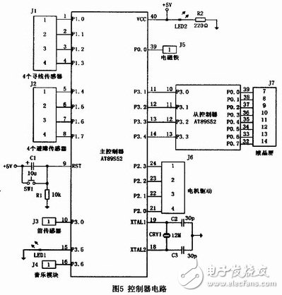
1.3 controller circuit
Since the main controller has many tasks, the circuit requires more pins, and the control program of the display is more complicated. We have a single MCU as the auxiliary part of the main controller, and share the work of the main controller through it. To complete the work of the display part. The connection between the main controller and other modules is shown in Figure 5.
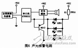
1.4 sound and light alarm circuit
The sound and light alarm module is mainly used in the search and rescue alarm circuit. At the same time, to further expand the application, we introduce another signal line while controlling its switch to realize the sound control. During the search and rescue process and when the safety arrives at the resettlement area, the sound is given by sounds of different frequencies and timbres. Looking for coins, we use metal detection sensors. When metal is found, its signal line level changes from low level to high level, triggering the microcontroller interrupt. Under the control of the single chip microcomputer, the robot stops moving, starts the music generation module and lights the LED. The sound and light alarm is performed, and the concrete realization circuit is shown in Fig. 6.
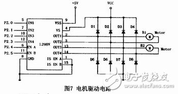
1.5 motor drive circuit
The MCU controls the robot to complete various actions by controlling the forward, reverse or stop of the motor through the feedback signal of the sensor. L298N is a special motor drive chip. It can realize various functions such as forward and reverse rotation, braking and pwm speed regulation of the motor. It is an ideal chip for controlling the robot motor. Therefore, we use L298N chip to control two common motors. . Through programming, you can control the basic requirements and functions of the realization of the problem, and also add various innovative functions. The signal power of L298N chip is separated from the driving power supply, and the voltage of the motor can be adjusted as needed. The driving circuit is shown in Figure 7.
1.6 display circuit
The corresponding information is displayed using the MSl602C-1 type LCD. The display module has an operating voltage of about 5V, supports display of 2 lines of characters, and can display 16 characters per line. Each character is displayed by 5&TImes; 7 dot matrix. A variety of displays can be realized by programming, and the display information is more than the digital tube, and the display effect is better.
Since the main controller has more MCU tasks and the circuit wiring is more complicated, we use a separate MCU to control the display module.
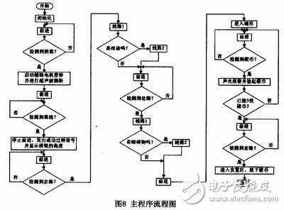
2 Software design of intelligent rescue robot
The software control part of the intelligent rescue robot adopts C language programming, and realizes the control function of the single chip AT89S52 by the powerful function of C language. The main program flow chart is shown in Figure 8.
3 Conclusion
Taking AT89S52 single-chip microcomputer as the core component, using infrared sensing detection, motor control and other technologies, through various discussions and attempts, and after several times the overall software and hardware combined debugging, the system is continuously optimized, and finally the intelligent rescue robot can Realize; avoid obstacles and find the right path; smoothly pass the damaged bridge, and can accurately measure the height of the bridge; automatically identify the route condition, and quickly make judgments based on real-time conditions to accurately control the robot Steering; automatically display the required information; automatically hunt forward, can intelligently detect, pick up, put down coins; sound and light alarm, and flashing lights; drive to the specified location automatically stop and display the end of the rescue.
In the design process, the hardware circuit is simple, the appearance is beautiful, and the advantages of software design are fully utilized to meet the requirements of the system.
Headset Battery,BT Headset Battery,Bluetooth Headset Battery,Headset Bluetooth Battery
Shenzhen Sunwind Energy Tech Co.,Ltd , https://www.sunwindbatterylm.com