The carrier frequency of an inverter refers to the frequency at which the power switching devices, such as IGBTs, are turned on and off. This parameter plays a crucial role in determining the performance and efficiency of the inverter. Here’s how it affects different aspects: 1. **Power Loss and Heat Generation**: As the carrier frequency increases, the power loss in the IGBT module also rises, leading to higher heat generation. This can be detrimental to the inverter's overall performance and lifespan if not properly managed. 2. **Output Waveform Quality**: A higher carrier frequency results in a smoother and more sinusoidal output current waveform, reducing harmonic distortion and electromagnetic interference. On the other hand, a lower frequency may cause the motor to experience reduced torque, increased losses, and higher temperatures. Conversely, excessively high frequencies can increase the inverter's internal losses and raise the IGBT temperature, while also increasing the voltage change rate (dv/dt), which can damage the motor's insulation. 3. **Motor Noise**: Increasing the carrier frequency typically reduces the noise generated by the motor. This is particularly beneficial in applications where quiet operation is important. 4. **Motor Heating**: Higher carrier frequencies tend to result in less heating of the motor, improving its efficiency and longevity. In practical applications, selecting the optimal carrier frequency involves balancing these factors. For motors with higher power ratings, it is generally advisable to choose a lower carrier frequency, especially when the load is not consistently high. This helps maintain efficiency while minimizing unnecessary stress on the system components.
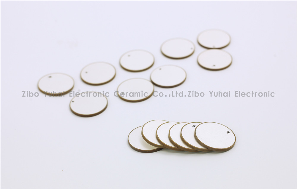
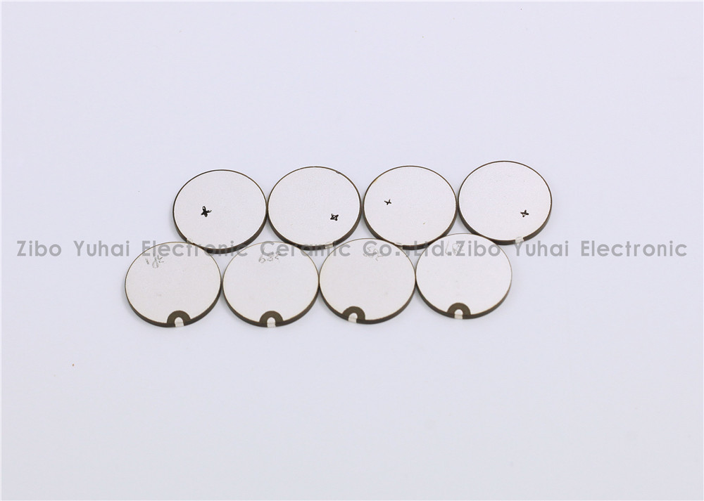
Piezoelectric Discs For Flowmeter Sensor
Piezoelectric ceramic disc
Quick delivery
High performance
Application: flow meter measurement
There are many kinds of USF used in closed pipeline according to the measuring principle, and the most commonly used are propagation time method and Doppler method. Among them, time difference ultrasonic flowmeter is used to measure fluid flow by the principle that the time difference of sound wave propagating downstream and countercurrent is proportional to the velocity of fluid flow. It is widely used in raw water measurement of rivers, rivers and reservoirs, process flow detection of petrochemical products, water consumption measurement of production process and other fields. According to practical application, time-difference ultrasonic flowmeter can be divided into portable time-difference ultrasonic flowmeter, fixed time-difference ultrasonic flowmeter and time-difference gas ultrasonic flowmeter.
Ultrasonic flow-meters use at least two transducers aligned so that ultrasonic pulses travel across the flow of liquid or gas in a pipe at a known angle to the flow.
Technical data:
Electromechanical coupling coefficient Kp: > 0.62
Dielectric Loss tg δ: <2%
Nominal Piezo discs for ultrasonic flowmeter:
OD14.2*1MHz PZT-51
OD14.6*1MHz PZT-51
OD15*1MHz PSnN-5
OD15*2MHz PSnN-5
OD20*1MHz PSnN-5OD20*2MHz PSnN-5
OD15*1MHz PZT-51
OD15*2MHz PZT-51
OD20*1MHz PZT-51OD20*2MHz PZT-51
Size, Frequency and Electrode on request.


Piezoelectric Ceramic Disc,Piezoelectric Disk Flow Meter,Piezoelectric Flow Sensor,Piezo Discs Flowmeter
Zibo Yuhai Electronic Ceramic Co., Ltd. , https://www.yhpiezo.com