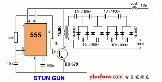
This circuit produces a very high voltage and must be used with care to prevent electric shock. The transformer can produce over 1000V and 8 stage voltage doublers and can produce up to 20KV DC high voltage.
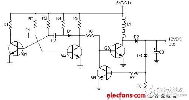
This 6v to 12v circuit is a simple circuit diagram that can deliver up to 800mA 12V power. Suitable for simple circuits such as motorcycle audio. Different output voltages can be changed by modifying some of the components in the circuit.
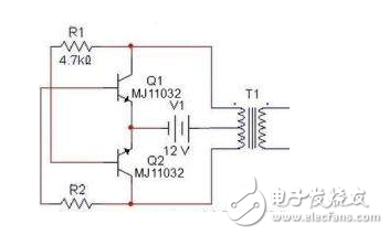
As shown in the figure below, we can also clearly see the required components and the connection between the various components. In addition to the transformer function, except for the transformer T1 for boosting and the power supply V1 for power supply, the remaining originals are rectangular. Wave circuit. In the choice of resistors, R1 and R2 are generally between 1.2k and 4.7k. There is no special requirement for the triode according to the capacity of the transformer. If the capacity is large, the power will be used. The transformer can be used as a normal control transformer. As long as there are two sets of 12V, we can In this schematic diagram, the selected device is transformer 0v-12V-12V, Darlington tube MJ11032 for triode, resistance 4.7k, output power can reach about 100W, not too small, but the power of the transformer should be selected. Otherwise the output power is not that big.
This inverter is mainly composed of a MOS field effect transistor and a common power transformer. Its output power depends on the power of the MOS FET and the power transformer.
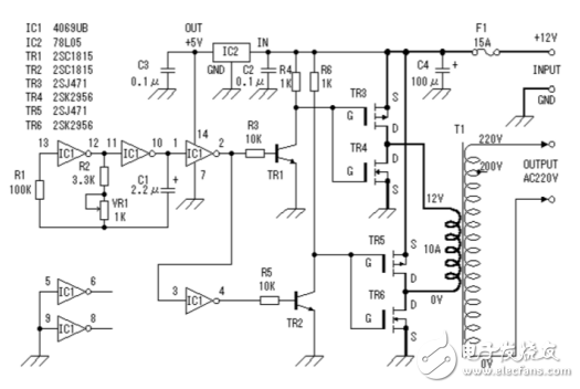
In the circuit diagram: 25T 310T 20T 250T is the winding turns of the transformer coil, VT1 is a high-power triode, can use the TV power supply tube, the resistance of R1 is 15-50Ω/5w, the resistance of R4 is 470Ω3W
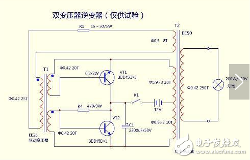
The transformer can be controlled by a 100W machine control transformer, the transformer core is taken apart, the secondary coil is removed, and the number of turns is recorded to calculate the number of turns per volt. Then rewind the secondary coil with a φ1.35mm enameled wire, first winding a 22V main coil, tapping in the middle, and then winding two 4V feedback coils with φ0.47 enameled wire. The layers of the coil are insulated with thick kraft paper. . After the coil is wound, the iron core is inserted, and the two 4V secondary wires are respectively connected with the main coil, and the end and the end are reversed. The voltage can be measured by the power. If the voltage increases after the connection between the 4V coil and the main coil, the connection is correct, and vice versa is wrong. You can change the connector.
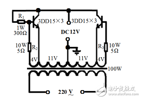
Two resistors R2 and R3 connected in series with the 4V coil can be made of resistance wire. The size of the resistor can be selected according to the output power. Generally, it is several ohms. When the output power is large, the resistance is smaller. The bias resistor uses 1W300Ω resistor. The resistor can also work, but it is better to pick one because the parameters of the tube are inconsistent and sometimes not vibrating. Triode selection:
Use three 3DD15s in parallel on each side to share six pipes. After the circuit is connected, check that there is no error. Then you can adjust the power. Connect the battery, find a 100W incandescent lamp to load, turn on the switch, and the bulb should be able to illuminate normally. Can not normally emit light, can reduce the base resistance, until it can normally emit light, then connect to the color TV to see if it can start normally, can not start normally also reduce the base resistance, after the adjustment is completed, it can be used normally.
A membrane switch consists of various layers laminated together. The layers of a basic membrane switch construction include: a membrane overlay, spacer, printer circuit, rear adhesive, and tail filler. Depending on the environment and requirements of the application into which the membrane switch plugs into, the construction can vary.
Membrane Switch Assemblies,Lcd Display Membrane Switch,Tactile Membrane Switch Keypad,Overlay Tactile Membrane Switch
KEDA MEMBRANE TECHNOLOGY CO., LTD , https://www.kedamembrane.com