(The customer's information and samples need to be kept confidential, this case only reflects part of the information)
Background of the project
A cable produced by a company had severe cracks before shipment, and the failure rate was as high as 80%. The direct cause of this failure is the replacement of new materials: the injection joint part is still polyether TPU, but the cable part is changed from the previous polyether TPU to polyester TPU. Based on this, the following failure analysis plan was formulated to give specific failure reasons and suggestions.
Main test items
Appearance observation
Thermal analysis
Molecular weight analysis
Additive analysis
Aging verification
1. Appearance observation
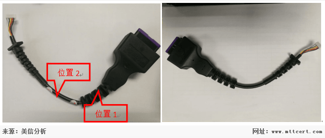
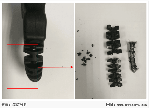
Based on the information provided, observe the entire sample. As shown in the figure, the coating layer in position 1 is a polyether TPU, and the lower layer is a polyester TPU cable jacket. The coating layer TPU material has good performance, soft and elastic, no cracking or stickiness. The lower polyester-type TPU cable is obviously cracked outside. Cut the cover layer, you can see that the lower polyester TPU material has become sticky and cracked. Position 2 is the polyester TPU cable jacket. Its surface is smooth, soft and elastic, without cracking or stickiness, and no whitening or cracking when bent.
Figure 1. Sample of polyester NG Figure 2. Sample of polyether OK
Based on the observed phenomenon: for the polyester TPU material of the cable cover, the physical properties of the polyester TPU material of the coated part are seriously reduced, and cracks occur; the physical properties of the polyester TPU material without the coated part are basically unchanged, No cracks.
2. Thermal performance analysis
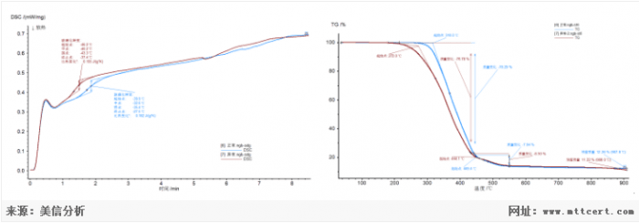
For the sample of polyester TPU cable material, take the polyester TPU material in position 2 (normal) and the polyester TPU material in position 1 (abnormal) for DSC and TGA analysis. The result is shown below.
DSC comparison chart TGA comparison chart
According to the DSC test spectrum of the sample, the glass transition temperature of the polyester TPU material in position 1 is -40.2 ℃, and the glass transition temperature of the polyester TPU material in position 2 is -32.6 ℃. According to the spectrum of the TGA test results of the samples, the initial decomposition temperatures of the polyester TPU materials in position 1 and position 2 are 316.0 and 272.0, respectively. The residual mass was 12.26% and 11.22%, respectively. It shows that the content of the decomposable components of the materials in position 1 and position 2 is basically the same, but the material composition has obvious differences.
3. Molecular weight test
The molecular weights of the polyester TPU materials in position 1 and position 2 were compared and tested. The results are as follows:
sample | Test items | result |
| | Mn | Mw | D |
Position 1 part TPU | Molecular weight | 9995 | 17772 | 1.95 |
Position 2 part TPU | Molecular weight | 37404 | 47548 | 1.27 |
From the relative molecular weight results, it can be seen that the molecular weight of the TPU material at position 1 has a significant decrease compared to the molecular weight of the TPU material at position 2, which directly indicates the degradation of the TPU material at position 1.
4. Sample plasticizer analysis
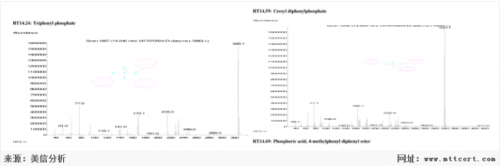
Using Py-GCMS, the additive of the coating material polyether TPU material in position 1 was analyzed.
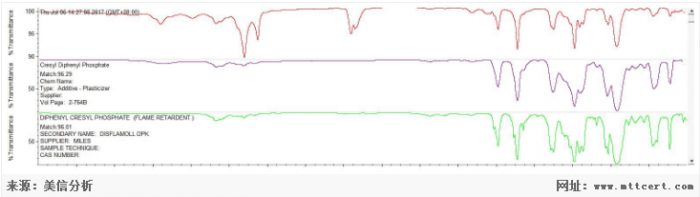
For the polyester TPU materials in position 1 and position 2, the additives were also separated by extraction and subjected to infrared analysis.
Combining the two results, it can be seen that tolylene diphenyl phosphate was extracted and separated from the polyester TPU material in the position 1 part. However, no phosphate esters were found in the polyester TPU material in the position 2 part. Since the polyester TPU material in position 1 and position 2 is the same raw material, the additive of the polyether TPU material in the comparison coating layer is phosphate ester, and it is considered that the additive with the coating layer penetrates into the polyester TPU material.
5. Aging verification
According to the sample processing information and the foregoing test results, the polyester TPU at position 1 was significantly degraded, and the polyester TPU at position 2 was not significantly degraded. The causes of degradation may be: 1. Water vapor degradation, 2. Thermal degradation during processing, and 3. Infiltration of additive degradation. For these three cases, a temperature accelerated aging test was designed.
1. Water vapor degradation: Take two parts of the TPU material at the location of the polyester TPU connector sample and the polyether TPU connector sample, and place it at a temperature of 60 ° C and a humidity of 90% for 14 days. Check the samples every 2 days for stickiness and cracking.
Results: to 14 days. The sample is soft and elastic. The surface is smooth, no stickiness, no obvious cracking.
2. Thermal degradation: Take two parts of the TPU material at the position of the polyester TPU connector sample and the polyether TPU connector sample, heat to 175 ° C, maintain for 34 seconds, and after cooling, place in a temperature of 60, 90% humidity, 14 days . Check the samples every 2 days for stickiness and cracking.
Results: to 14 days. The sample material of the polyester TPU joint is soft and elastic, without stickiness, and the surface has tiny cracks. The sample of polyether type TPU joint is soft and elastic, the surface is smooth and clean, no stickiness, and no obvious cracking.
3. Additive degradation: Take two parts of the TPU material at the position of the polyester TPU joint sample and the polyether TPU joint sample, immerse them in the phosphate ester substance, and check whether the sample is sticky or cracked after 48 hours.
Result: The sample material of the polyester TPU joint is slightly tacky. There is no obvious change in the surface of the sample material of the polyether TPU joint.
to sum up
Summarizing the above tests, from the appearance and test observations, the polyester TPU material under the coating layer has undergone significant degradation leading to cracking, and the polyester TPU material without the coating layer has significantly degraded at the end. Through the analysis of the additive composition, it can be seen that the phosphate flame retardant of the polyether TPU of the coating layer has penetrated into the polyester TPU material of the lower layer (the phosphate T substance is not included in the polyester TPU without the coating layer) ).
Through water vapor aging and heat aging, no degradation phenomenon was found for the time being. The degradation aging test of additives was carried out, and it was found to have a corrosive effect on the polyester TPU material, but no obvious corrosion effect on the polyether type material.
MTT is a third-party laboratory engaged in the quality inspection, identification, certification and failure analysis services of materials and components.
PGA Sockets Adapters
PGA Sockets Pin Grid Array Socket
A pin grid array, often abbreviated PGA, is a type of integrated circuit packaging. In a PGA, the package is square or rectangular, and the pins are arranged in a regular array on the underside of the package. The pins are commonly spaced 2.54 mm (0.1") apart, and may or may not cover the entire underside of the package.
PGAs are often mounted on printed circuit boards using the through hole method or inserted into a socket. PGAs allow for more pins per integrated circuit than older packages, such as dual in-line package (DIP).
PGA Sockets & Adapters
Low insertion force Pin Grid Array (PGA) Sockets and Adapters are available in a variety of RoHS Compliant insulators with hundreds of screw-machined terminal choices. Virtually any PGA footprint can be accommodated, including interstitial patterns.
PGA Sockets & Adapters Overview
Durable construction for virtually any application
Wide variety of materials, lengths, and sizes
Cost-effective method for replacing, repairing, or upgrading PGA devices
Unique options such as solder preform terminals eliminate the need for wave soldering in mixed SMT/Thru-hole applications
RoHS compliant insulators and screw-machined terminals are compatible with lead-free processing - select either Matte Tin/Gold (MG) or Gold/Gold (GG) plating
Antenk's Pin Grid Array (PGA) Sockets
Complex printed circuits are too valuable to risk direct soldering to expensive integrated circuits (ICs). Using a socket is the answer. The use of sockets offers advantages that prove cost effective and simplify board design.
Antenk's processor socket line is designed for use with Intel- and AMD-based microprocessor packages. Socket types include land grid array (LGA), micro pin grid array (mPGA), and PGA with low to zero insertion force. The mPGA and PGA sockets are designed for various microprocessor packages for notebook PCs, desktop PCs, and servers. For custom applications, the compression sockets can be configured to the specific application.
mPGA/PGA (ZIF)
These sockets provide a zero insertion force (ZIF) PGA interface to the microprocessor PGA package and are attached to the PCB with surface-mount technology (SMT) soldering. PGA sockets are available in arrays up to 989 positions with single lever, screw driver, and hex wrench actuation methods.
PGA Sockets (LIF)
These sockets are primarily employed for microprocessor package test applications using through-hole solder attachment to the PCB design. The contacts are screw-machine outer sleeves with either stamped and formed or drawn inner contacts. Custom arrays are available in more than 1,000 positions.
Pin Grid Array (PGA) Sockets Type
mPGA
PGA

PGA Sockets Typical Applications:
Eliminate hand-loading of pins, facilitate solder joint visibility, low profile component mounting or board mating.
PGA Sockets,mPGA Sockets,Integrated Circuits Socket,Pin Pga Sockets,Pga Socket Connector,PGA Adapters,Pin Grid Array Sockets,Processor Socket
ShenZhen Antenk Electronics Co,Ltd , https://www.antenkelec.com