Abstract: The probe is the first link of the observed signal. The main function is to carry the signal transmission link, and the signal to be tested is transmitted to the oscilloscope completely and reliably for measurement and analysis. But do you know how to achieve the best match of the probe?
Probe classification
Probes are usually classified by measurement object, as shown in Figure 1. Among them, high-impedance passive probes, high-voltage differential probes and current probes are the most familiar to us. Let's take a brief introduction.
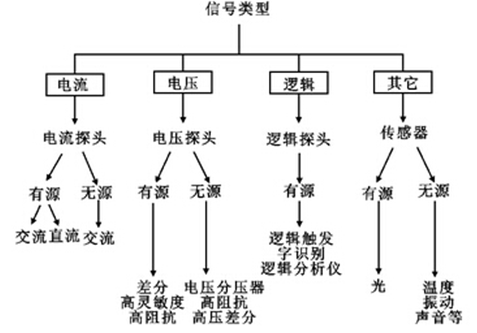
Figure 1 Probe classification
1.1 1.1 High-impedance passive probe
In terms of actual demand, the high-resistance passive voltage probe with compensation has the largest proportion of use, which can satisfy most low-speed digital signals, power supplies and other typical oscilloscopes.
Such probes have a high input resistance (generally 1 MΩ or more) and an adjustable compensation capacitor. When first connected to the oscilloscope, it is generally necessary to adjust the capacitance value with an adjustment rod to match the oscilloscope input capacitance to eliminate low frequency or high frequency gain. The left side of Figure 2 is the undercompensated waveform with the normal waveform in the middle and the overcompensated waveform on the right.
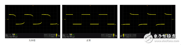
Figure 2 Passive probe compensation
For example, ZDS2024PLUS comes standard with ZP1025S high-resistance passive voltage probe. The specific parameters are as follows:
Table 1 ZP1025S specification model 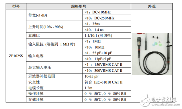
1.2 1.2 High Voltage Differential Probe
First, the concept of differential is introduced: differential signals are referenced to each other, not to grounded signals. The high-voltage differential probe consists essentially of two symmetrical voltage probes with good insulation and high impedance to ground, providing a high common-mode rejection ratio over a wider frequency range, allowing for two points between arbitrary The floating signal is converted into a signal to the ground, which is mainly used for testing in the switching power supply industry. The schematic diagram is shown in Figure 3.
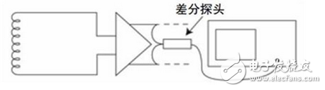
Figure 3 Principle of high voltage differential probe
The following table shows the specific parameters of common high voltage differential probes:
Table 2 Specifications of common high voltage differential probes 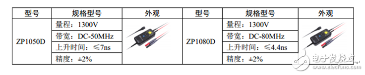
1.3 1.3 Current Probe
The current probe uses the Hall sensor and the induction coil to measure the DC and AC current. The working principle is to convert the current signal into a voltage signal, and the oscilloscope collects the voltage signal and displays it as a current signal.
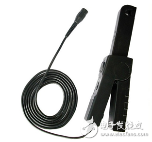
Figure 4 current probe picture
The advantage of the current probe is that current measurement can be performed without disconnecting the power supply line. Typical applications are system power measurement, power factor measurement, and on/off waveform measurement of the switch. The main disadvantage is that the measurement capability of its small current is limited by the bottom noise of the oscilloscope, so the small current measurement capability is limited.
2. How to choose the right probe?
The above is a brief introduction to some common probes, so how to choose a suitable probe? Which parameters of the probe are concerned about?
1. Impedance matching: The input impedance of the probe should match the input impedance of the oscilloscope used to reduce the load on the circuit under test. For oscilloscopes with low input impedance, select active probes or probes with 50Ω input impedance; for oscilloscopes with high input impedance, select &TImes;10 probes. For example, the input impedance of the oscilloscope is 1MΩ/10pF, and the input impedance of the probe is preferably 10MΩ/1pF. Such a probe has 10 times of signal attenuation, has a small load on the signal under test, and can match the input impedance of the oscilloscope.
2. Bandwidth: The bandwidth of the probe should be equal to or greater than the bandwidth of the oscilloscope. If you observe a pure sinusoidal signal, the probe bandwidth is equal to the highest value of the measured signal frequency; if you observe a non-sinusoidal signal, the probe bandwidth should accommodate the fundamental and most important harmonic components of the signal under test.
3. Rise time: In order to accurately measure the rise and fall times of the pulse, the rise time of the system (ie, the sum of the rise time of the oscilloscope and the probe) should be 3-5 times faster than the rise time of the measured signal.
3. Summary
To ensure the accuracy of the test results, the probe is required to have the least impact on the circuit under test, and the maximum signal fidelity is transmitted to the oscilloscope. If the probe changes the signal or the mode of operation of the circuit under test in any way, the oscilloscope will see the distortion of the actual signal, which may result in erroneous measurements or misleading measurements. Only the probe that matches the oscilloscope and the circuit under test is your best choice!
Electric Ceramic Cooktop,Ceramic Surface Cooktop,4 Heating Zone Ceramic Cooktop,4 Burners Gas Cooktop Freestanding
xunda science&technology group co.ltd , https://www.gasstove.be