Current source circuit [1] howland current source circuit (1)
The first section begins with a howland circuit I recently designed. One project required changing the AC voltage signal to an AC current signal with an output of +/- 50 mA for long distance transmission. The input signal is a 50 Hz ac voltage signal with a valid value of +/- 5V. Signal error should be kept within 1%. Power supply is available from +/-12V to +/15V. This circuit can be designed with discrete components to drive a Class AB amplifier with an op amp. The output of the class AB amplifier is connected in series with a resistor as a sampling resistor. The voltage signal formed by the current flowing through the sampling resistor is the feedback signal. This design has outstanding shortcomings, using more discrete devices, the output is too complicated, and it is not easy to control the accuracy. So this article recommends a simpler circuit - howland current source circuit. The basic schematic of the Howland circuit is as follows: where X1G represents the ideal op amp.
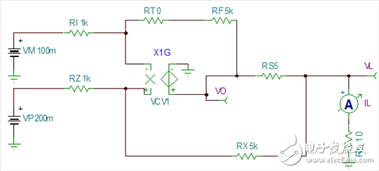
According to the virtual short and virtual break characteristics of the ideal op amp, we can deduce the relationship between the output current of this howland circuit and the input voltage VP, VM as follows: [2]
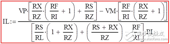
In the actual circuit design we usually make RX = RF and RZ = RI. So the above formula can be simplified as:
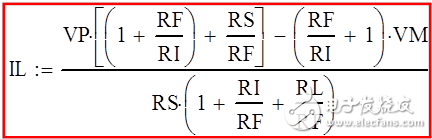
The signal input to the circuit is a unipolar voltage signal, which can ground the VM, that is, the voltage is zero. This further simplifies the formula to determine the value of each resistor.
Current source circuit [2] howland current source circuit (2)
Howland circuit design principles. The scheme design is as follows:
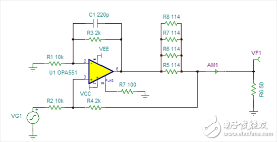
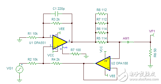
The circuit uses a large current op amp OPA551 that can output up to 200mA. A single op amp is used to achieve high precision positive and negative current outputs. The maximum offset voltage of the OPA551 is 5mV. The maximum input signal required by this design is 7.071V. Therefore, the effect of the offset voltage will be less than 0.1%. The voltage signal formed by the four high-precision resistors R5-R8 through which the current flows is fed back as a feedback signal to the positive input terminal resistor R4. The reason for using four resistors is that the four resistors can share the output current, ensuring that the heat generated by the resistor is much lower than the rated power; this can match the more accurate resistance. In realizing production, the random error of the resistance can also be reduced. In order to ensure the accuracy, it is recommended to use a resistance value of 0.1% (one thousandth) precision for the resistance value of R1-R4. C1 is used to limit the circuit bandwidth while at the same time filtering the noise at a higher frequency.
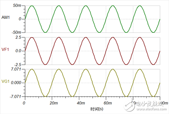
Next, we simulated it with TI's free simulation software TINA. The simulation results are as follows: From the simulation results in the coming year, the design error will be less than 0.2%.
This circuit can be further improved. As shown in the figure below, the feedback voltage signal is fed back to R4 via a high-precision op amp OPA188. This ensures that the feedback signal is not affected by the input signal. In the figure, U1 and U2 both introduce negative feedback, the former constitutes an in-phase summation operation circuit, and the latter constitutes a voltage follower.
In the actual board test process, the accuracy will have a slight impact, so it is recommended to fine-tune the value of the feedback resistor to ensure accuracy after the PCB is produced. To achieve higher precision.
8Dn9 Gas Insulated Metal Enclosed Switchgear
Square D Switchgear,Switchgear For Generator,Metal Switchgear,Siemens Switchgear Products
Shandong Shunkai electrical equipment co., LTD. , https://www.chinasdsk.com