1 system principle and structure
This article refers to the address: http://
1.1 System function introduction
The system can automatically collect the ambient temperature and light intensity of the scene at 10 times/s, collect the opening and closing state of the air conditioner and the curtain, and display it in real time through the LCD screen. The temperature sensing range is -55 to +125 °C with an accuracy of ±0.5 °C. The intensity range of light intensity is divided into strong, strong, medium, weak, and weak. The status of the air conditioner and curtains is on or off.
The user can communicate wirelessly between the system connected to the GSM module through a mobile phone or a PHS terminal, and the communication range is all ranges covered by the mobile network, so that the true communication range is infinite. The specific communication is:
1) When the system detects that the temperature and light intensity exceed the set standard value, it will automatically send the over-subscribed Chinese prompt message to the user's mobile phone.
2) The user can send a Chinese text message to the system to query the temperature, light intensity, air conditioning and curtains in the car in real time.
3) The user can send control signals to control the three actions in the car: 1 pull up the curtains and open the curtains. Pulling the curtain is given by the MCU to the LG9110, driving the motor, through the motor forward and reverse to achieve the action of pulling the curtain and opening the curtain. 2 Start the air conditioner and stop the air conditioner. The LG9110 is given a high level by the single-chip microcomputer to drive the fan blades on the DC motor to simulate the start and stop of the car air conditioner. 3 Start the engine and stop. The engine is simulated by an electric motor, which is controlled by a single-chip microcomputer to rotate and stop the start and shutdown of the simulated automobile engine.
1.2 system solution
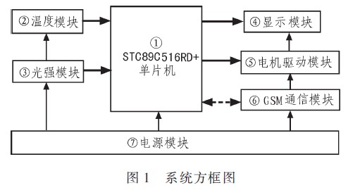
The design hardware circuit comprises a power module, a control module, a temperature module, a light intensity module, a display module, a motor drive module and a GSM communication module. The relationship between the modules is shown in Figure 1.
1.2.1 Main control system module
The main control system module uses the 51 core-based STC89C516RD+ MCU produced by Hongjing Technology to complete the signal acquisition, control and communication functions. It has 64K on-chip FLASHROM and 1280B on-chip RAM resources, and has a 51 core, which is very cryptographic. Strong, the ISP download method is simple and easy to use, and the storage capacity is large, which is very suitable for development and design.
In this design, the STC89C516RD+ MCU acts as the control core. Firstly, the external sensors are used to collect data from various external sensors, and then they are analyzed and compared with the internal reference data through different adaptive algorithms of each input module. The warning message is sent to the car user through the GSM/CDMA network, and the car user can also send various information of inquiry and control to the system through the GSM/CDMA network.
1.2.2 Temperature Module
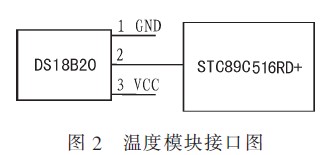
The temperature module uses the DS18B20 one-line digital temperature sensor manufactured by DALLAS. The DS1820 digital thermometer provides a 9-bit (binary) temperature reading to indicate the temperature information of the device. It is sent to the host CPU via a single-wire interface and the measured temperature is -55 to +125 °C. The interface circuit between the temperature module and the main control CPU is shown in Figure 2.
1.2.3 Light intensity module
The light intensity module converts the analog signal generated by the photoresistor induced light intensity into a digital signal sample to the single chip microcomputer through the ADC0832, thereby realizing the collection of the light intensity data in the vehicle.
1.2.4 LCD display module
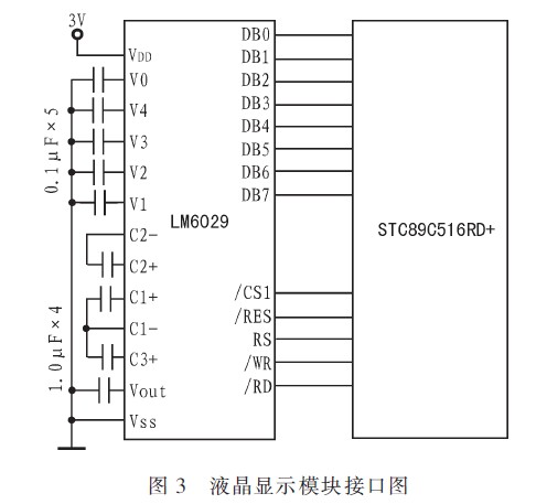
The display module uses the LM6029LCD display with a Chinese character library to display the output. LM6029 dot matrix graphic liquid crystal display module adopts S680724 controller, the number of dot matrix is ​​128x64, comes with Chinese character library, and uses 8bit parallel interface to connect with main control CPU. The interface circuit of display module and main control CPU is shown in Fig. 3.
1.2.5 Motor Drive Module
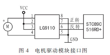
The DC motor is driven by the LG9110 driver chip. It can control the forward and reverse rotation of the DC motor through the control line, thus controlling the action of the external output device. The interface circuit between the motor drive module and the main control CPU is shown in Figure 4.
1.2.6GSM module
The GSM module adopts the TC35 produced by Siemens, and has the function of sending and receiving short messages in both Chinese and English. The TC35 is a new generation of wireless communication GSM module from Siemeils. With RS232 communication interface, it can easily communicate with PC and MCU. Data, voice transmission, short message service (ShortMessageSer-vice) and fax in the system solution can be implemented quickly, safely and reliably. The TC35 module operates from 3.3 to 5.5V and can operate in both 900MHz and 1800MHz bands. The power consumption of the TC35 module is 2W (900M) and 1W (1800M).
The TC35 uses an RS232 level interface that can be directly connected to a PC. In this design, a TTL to RS232 level circuit is required between the UART of the master CPU and the TC35.
1.2.7 Power Module
The power module uses LM2576DC/DC DC step-down Switching Power Supply, which can reduce the DC voltage of the +12V cigarette lighter to various DC voltages such as +5V and +3.3V to supply power to other modules.
1.3 Software Process
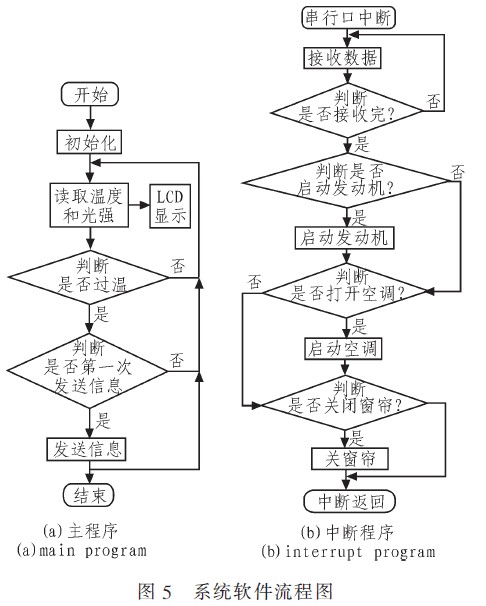
The system software is divided into 4 parts. The first part is DS18B20 temperature sensing, the correct timing reading and output information needs to be set; the second part is light sensing, using ADC0832 to convert the analog voltage value induced by the photoresistor into digital signal and send it to the single-chip microcomputer; the third part is The LM6029 display, which displays the status of the car through a single-chip control; these three parts constitute the main program. The fourth part is the GSM module. The MCU interrupts receiving and transmitting the communication information of the GSM module through the serial port. The system flow chart is shown in Figure 5.
2 system test
2.1 test plan
System testing uses a module-by-module debugging and testing approach. First use a multimeter to test whether the output of the power module is 3.3V and 5V of the system design; then download the minimum system of the MCU through ISP; then connect the LCD module to test whether it can display normally; then connect the light intensity sensor and temperature sensor to test the temperature. Whether the light intensity is proportional to the collected value; then test whether the curtain, air conditioner and engine simulation system can work normally under the normal working condition of the power module; finally, use the serial port debugging of the PC and the serial communication between the GSM module.
Connect the whole system, connect the power module to the Power Supply, repeat the above steps, send the information to the GSM module through the mobile phone, send the inquiry command, observe the information data received by the mobile phone and the data and display displayed on the LCD display. Whether the data is consistent. Send control commands to observe whether the system will rotate the analog engine and air conditioner according to the user's request, and whether the curtains will automatically pull up and close. Through the above test, you can judge whether the whole machine is running normally.
2.2 test data
The test data includes the following four parts:
1) Test the output of the power module through the multimeter, the error of +5V and +3.3V is within ±0.1V, and the current output after reaching all loads reaches +2A;
2) By setting different standard status values, the test to the system exceeds the standard and automatically send SMS to the terminal function normally;
3) sending a query command to the system through the terminal, and testing that the information data received by the mobile phone and the data displayed on the LCD display are completely consistent;
4) Send the control information to the system through the terminal, and test that the action of the air conditioner and the curtain controlled by the motor is the same as the command.
2.3 Analysis of results
After various performance tests, the system's indicators and parameters have basically achieved the expected results. If the actual car air conditioning and engine interface can be considered, the system will be more perfect and worthy of promotion.
3 conclusions
The characteristics of this project have the following two aspects:
1) The system can automatically transmit the over-standard information in the car to the user terminal through the GSM network, or can remotely query and control the user outside the vehicle to overcome the inconvenience caused by the distance between the user and the car. Sex
2) The system can automatically collect various parameters in the car, automatically compare it with the standard parameters set by the user, automatically notify the user when the standard exceeds the standard, and can automatically identify the query information and control information sent back by the user, which can be based on the postback. The query information is sent in real-time state, and the control information of the postback can be automatically converted into a control command, and the whole system has the characteristics of artificial intelligence.
Dimmable Class 2 Led Driver is the most compact 12V/24V DC Dimmable Led Driver on the market with UL 8750 listed. The series led driver is class 2 rated and designed to operate with any standard MLV/Incandescent TRIAC (Leading edge) dimmer switch. Encased in a low profile coated metal box that includes 2 knock-outs, one on each side, to enable easy installation that complies with electrical code requirements.
Dimmable Class 2 Led Driver
Waterproof Led Driver,Led Driver Zf120A,75W Dimmable Led Driver,Led Driver Dimmer 220V
Shenzhenshi Zhenhuan Electronic Co Ltd , https://www.szzhpower.com