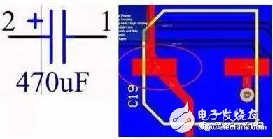
1. Is there a polarized capacitor, and are the schematic and PCB reversed?
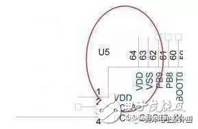
2. The power supply and ground were forgotten to be connected. There is also a reversal.
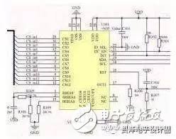
3. The connector's wiring order is reversed.

4. RX and TX are reversed. Please make sure not to reverse them when drawing the serial port. If you do, the board will fail testing and the serial communication won’t work.

5. I once created a package, but the device wasn’t available. I tried to download the datasheet from Baidu, but couldn’t find it for purchase.
6. I directly copied a circuit, but the components couldn’t be sourced.
A team once made a smart lock by copying Samsung’s design. Unfortunately, they couldn’t find a capacitive touch controller in Korea, no agent or support was available. They had to test and figure everything out on their own.
7. When choosing a capacitor, I only considered the capacitance and ignored the voltage rating. As a result, the large package couldn’t fit the required capacitor.

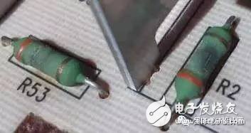
8. When selecting a resistor, I only focused on the resistance value, not the power rating.
9. After finishing the PCB layout, I didn’t check the DRC report and relied on visual inspection. When the board came back, there were actual flying traces.
Once, I disabled the short-circuit DRC check, and as a result, the power supply ended up with reversed polarity.
10. The package was mirrored.
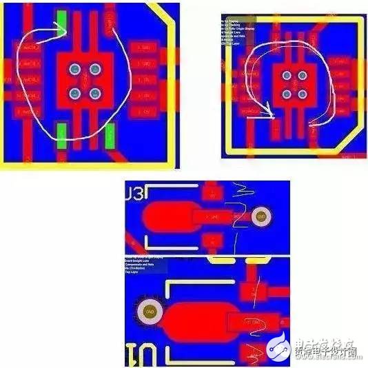
I was in a rush, didn’t get the chip, just looked at the datasheet and drew the layout. When the board arrived, I noticed the mirrored package. But this isn’t my fault—some datasheets show a bottom view without specifying it clearly!
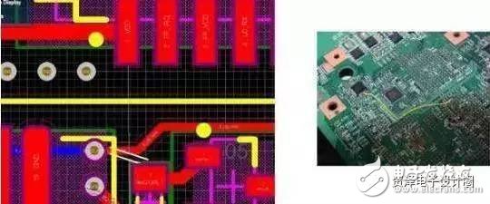
11. The thermal pad’s solder mask wasn’t processed.
12. The LM1117 was completely reversed. The INA826 was drawn incorrectly on the schematic. When I burned the program, I forgot to select the external crystal oscillator. I spent a long time debugging before realizing I had messed up the programming.
13. The 431 regulator is tricky. I always double-check the pin order every time.
The pin arrangement of the SOT23 package for the 431 regulator varies by manufacturer. For example, TI-TL431A uses CAR, while UTC-TL431A and CJ431A use RAC. Some even have different pinouts. The datasheet usually shows a bottom view, so if you don’t mirror it during layout, the component ends up on the back of the board.
14. I once reversed the package according to the datasheet and said it was the most beautiful layout I had ever done.
15. Whenever there’s a daughter card on the board, I start sweating and can’t sleep well, worried about potential issues.
16. The battery interface was reversed, which led to a big loss.
Common Eight Misunderstandings in Circuit Design
Phenomenon 1: This PCB doesn’t require high design quality, so just use thin lines and auto-route it.
Comment: Auto-routing takes more space and creates more vias than manual routing. In mass production, PCB manufacturers consider line width and via count when reducing costs. These factors affect yield and drill bit usage, helping reduce supplier costs and justify lower prices.
Phenomenon 2: These bus signals are pulled with resistors, and I feel relieved.
Comment: Not all signals need pull-ups. Pull-down resistors for simple inputs consume microamps, but for driven signals, current can reach milliamperes. For example, a 32-bit bus with pull-up resistors can consume several watts, leading to unnecessary power waste.
Phenomenon 3: What should I do with these unused I/O ports on CPU and FPGA? Just leave them empty for now.
Comment: Leaving unused I/O floating may cause oscillations due to interference. MOS devices consume power based on gate flips. Pulling up each pin adds microampere current, so setting them as outputs (without external drive) is better.
Phenomenon 4: There are many unused logic gates in this FPGA, so let’s use them.
Comment: FPGA power consumption depends on the number of flip-flops and switching activity. Even the same model can vary by 100 times depending on the design. Reducing flip-flop usage is key to lowering power consumption.
Phenomenon 5: These small chips consume very little power, so we don’t need to worry about it.
Comment: Determining internal power consumption is hard. It mainly depends on pin current. An ABT16244 consumes less than 1 mA without load, but each pin can drive 60 mA. That means up to 960 mA total, causing significant heat.
Phenomenon 6: There are so many control signals in memory. I only need OE and WE, and grounding CS makes reading faster.
Comment: Most memory power is consumed when the chip select (CS) is active. Using CS to control the chip reduces power. Shortening the pulse width of CS can further save energy.
Phenomenon 7: Why are there overshoots on these signals? As long as the match is good, they can be eliminated.
Comment: Overshoots are common, especially in TTL, LVDS, and RS422. Unless they’re extreme, matching might not be necessary. Matching resistors can cause excessive current and signal distortion. A good match is acceptable as long as overshoots are within limits.
Phenomenon 8: Reducing power consumption is a hardware issue, not software’s responsibility.
Comment: Software controls almost every chip access and signal flip. Optimizing code—using more register variables, internal cache, and timely interrupt handling—can significantly reduce power consumption.
Flat Cable,Tpe Flat Data Cable,Usb Data Charging Cable,4-Core Usb Data Cable
ShenZhen Puchen Electronics Co., Ltd. , https://www.szpuchen.com