With the rapid development of EDA technology, the design technology and tools of electronic systems have undergone profound changes. The emergence of large-scale programmable logic devices CPLD/FPGA has brought many conveniences to designers. Using it for product development, not only low cost, short cycle, high reliability, but also full intellectual property. This paper introduces a taxi meter system with Altera's programmable logic chip EPM7128SLC84-15 as the control core and additional peripheral circuits.
1 system composition
The composition of the taxi meter based on CPLD/FPGA is shown in Figure 1. The main functions of each part are as follows: (1) The A counter counts the pulse signal sent by the wheel sensor (one pulse per revolution). The wheel diameters of different models may be different. The model is selected by “Setting 1†to adjust the car with different wheel diameters. (2) The B counter accumulates the 100-meter pulse and outputs the actual number of BCD codes to the decoding dynamic scanning module. A pulse is sent to the C counter every time 500 is counted. "Setting 2" implements pre-fabrication of the starting kilometers. (3) The C counter realizes an accumulated count with a variable step size (ie, the unit price is adjustable), and is charged once every 500 meters. "Setting 3" is used to complete overcharging, starting price prefabrication, etc. (4) Decoding/Dynamic Scan The digital tube is driven by dynamic scanning after decoding the value of the distance and cost. (5) The digital tube display displays the number of kilometers and the billing amount by four LED digital tubes (three digits, one decimal place). 
2 functional module design
The taxi meter consists of the vehicle model adjustment module, the meter module, the billing module, the decoding dynamics and the scanning module. The whole system adopts the modular design. First, the function module is written in VHDL, and then the function modules are used in the top schematic. connect them.
2.1 Model adjustment module
Taxi models are not single, and the tire diameters of each model are also different. According to the survey statistics, the current taxi tires have roughly four diameters, which are 520mm, 540mm, 560mm and 580mm. To enable a taxi of different models to send a pulse every 100 meters, it can be done by setting the coefficient of the "prefabricated frequency divider". The frequency division coefficients calculated based on the above wheel diameters are 61, 59, 57, and 55, respectively. The prefabricated data is controlled by two vehicle setting switches. The correspondence between DIP switch status and wheel diameter is shown in Table 1 ("1" is high level and "0" is low level).
Table 1 Model settings 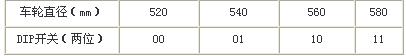
In parameter prefabrication, use the With_Select statement (table lookup method) to do the crossover selection:
With cartype select
Typecounter<="111101"when "00", --520mm
"111011" when "01", --540mm
"111001" when "10", - 560mm
"111000" when "11", --580mm
"000000" when others;
The divider uses an add-drop circuit whose duty cycle can be adjusted by datal(x) and the divider has a “startâ€/“clear†terminal (high clear). The timing simulation waveform is shown in Figure 2. As can be seen from the figure, for the model with the switch set to "10", when the 57th pulse arrives, the oclk terminal of the module goes from high to low and outputs a low level signal. The model adjustment module (hereinafter referred to as FP) package is shown in Figure 4.
2.2 Tax module
The metering module is an addition counter with a mode of 10 and a step size of 1. The module can pre-set parameters such that after the actual count value is greater than the pre-made value, a pulse is sent every 500 meters, and the count value is sent to the decoding dynamic scanning module for display. The prefabricated parameters use uncompressed BCD codes, so the six states of binary 1010 to 1111 must be skipped during counter design. In the VHDL program, use the IF statement to achieve.
If km(3 downto 0)=“1001†then km:=km+“0111â€:
Else km:=kin+1;
End if;
The metering module also has a "start" / "clear" end. Parameter prefabrication also uses the With_Select statement. The correspondence between "starting mileage" and "switch setting" is shown in Table 2. The metering module (hereinafter referred to as MILE) package is shown in Figure 4.
Table 2 Starting mileage setting 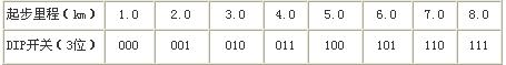
This article refers to the address: http://
2.3 Billing Module
The billing module is an adder that has a modulus of 10 and a variable step size. The module pre-forms the step size through the switch and changes the step size when a certain pre-fabrication parameter is exceeded. The billing module also uses the uncompressed BCD code, but since the step size is not 1, it must be adjusted when doing the uncompressed BCD addition, otherwise it may cause an overtravel error when the preset parameters are exceeded or not exceeded. Here, the AF flag of the microcomputer is used, and a semi-carry flag is set therein, and when the accumulated sum is greater than 9 or the semi-carry flag is "1", the accumulated sum is adjusted.
If datal(3 downto 0)>9 or datal(4)='1'then
Datal(3 downto 0):=datal(3 downto 0)+"0110";
Datal(8 downto 5):=datal(8 downto 5)+1;
End if;
Among them, data (4) is a semi-carry flag. The "starting price" and "overpriced plus fee" setting parameters are shown in Tables 3 and 4, respectively. The billing module (hereinafter referred to as MONEY) package is shown in Figure 4.
Table 3 Start price setting 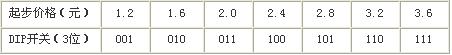
Table 4 Over-price plus fee setting 
2.4 display module
The display module consists of seven segments of LED digital tube decoding and dynamic scanning display.
2.4.1 Seven-segment LED digital tube decoding
This design uses a common cathode seven-segment digital tube. According to the correspondence between the hexadecimal number and the seven-segment display segment code table, VHDL's With_Select or When_Else statement can be used to facilitate their decoding. 
2.4.2 Dynamic Scan Display
Dynamic scanning is based on the principle of visual persistence of the human eye. As long as the scanning frequency is not less than 24 Hz, the human eye does not feel the flicker of the display. The 24 Hz scan pulse of the system is provided by the corresponding peripheral circuit. The key to the design of the dynamic scanning circuit is that the bit selection signal should be in one-to-one correspondence with the displayed data, so the synchronization pulse signal must be provided in the circuit. Here, the octal counter is used to provide the sync pulse. The VHDL block is as follows:
cIkl_label:PROCESS(scp)
BEGIN
IF scp'vent and scp='1'THEN count<=count+1;
END IF;
END PROCESS clkl_label;
The selection of the display data is controlled by the counter, and the VHDL block is as follows:
Temp<=counterl when count=“000†else. . .
Counter4 when count=“011†else
Milel when count=“100†else. . .
Mile4 when count=“111â€;
The timing simulation of the bit selection signal is shown in Figure 3. As can be seen from the timing simulation diagram and the above procedure, the bit selection signal and the data to be displayed are synchronized. 
The display of the decimal point in the dynamic scanning circuit cannot be completed in the decoding circuit. Since the position of the decimal point is fixed, the synchronization signal provided by the counter can generate another signal to control the DP. The VHDL program is implemented as follows:
If (count: "101" or count = "001") then data(0)<='1';
Else data(0)<='0';
End if;
The display module (hereinafter referred to as SHOW) package is shown in Figure 4. Two procedures are applied in this module, in which the program executes sequentially, with the first process triggering the second process.
3 System integration
3.1 Module joint adjustment
After the design of each function sub-module is completed, each function sub-module (.sym) is connected by using the MAXPLUSII Graphic Editor. Because there is a burr in the MILE module, it cannot be directly connected to the latter stage. By adding a delay to the output pulse signal and then "and" with the original signal, the glitch can be eliminated. The top schematic of the system is shown in Figure 4.
Chip pin definitions can be edited directly. The pin file is either under the Floor-Plan Editor. After completing the pin definition, select the device (EPM7128SIC84-15) and generate it after compilation. Sof,. Pof and report files. Rpt. View the report file to get the usage of the device pins and the internal resources of the device. Optimize resource configuration by replacing the appropriate device. The general principle of selecting a device is that the resources used by the system should not exceed 80% of the device resources. If it exceeds 90%, the system power consumption will increase and the operation will be unstable. According to the report of this design device, 16 input and output pins are used, and the chip resource utilization rate is only 51%, which has a large expansion space. 
3.2 Hardware Design Description
The taxi meter counting pulse CP of this design comes from the wheel speed sensor (reed switch), the pulse is sent through the internal shaping of the device, and the dynamic scanning pulse is given by the peripheral circuit; the system uses rectification, filtering, and step-down. Taxi power supply; due to the limited driving capacity of CPLD/FPGA, in order to enhance the brightness of the digital tube and improve the reliability of the system, the current drive devices ULN2803 and 2SCl015 are added to the LED driver and the bit driver respectively.
Field experiments show that the meter realizes automatic billing according to pre-made parameters (maximum billing amount is 999.9 yuan), automatic metering (maximum km-km is 999.9 km), etc. Pre-fabrication of parameters per kilometer, model and mileage increase (eg starting price of 5.00 yuan; after 3 kilometers, 1.20 yuan / km; billing more than 15.00 yuan, 50% of the car per kilometer) Fees, etc.), and the preset parameters can be adjusted in a wide range. Due to the adoption of CPLD/FPGA large-scale programmable logic device, the whole machine has low power consumption, strong anti-interference ability, stable system, reliable operation and convenient upgrade. In addition, according to actual needs, the system can easily add the following functions: 1 increase the clock function through internal programming of the chip (the internal resources of the device are sufficient), which can provide convenience for drivers and passengers, and provide reference for automatic adjustment of charging standards at night; 2 Use the output lead of the CPLD/FPGA to control the voice chip, which can send greetings to the passengers, remind the passengers to tell the driver where to go, and report the fees that should be collected.
Polyvinyl Chloride (PVC) insulated Electrical Cable is used in fixed wiring. As PVC is a thermoplastic polymer, PVC properties make it suitable for applications where the cables may be exposed to high or low temperatures. PVC insulation is frequently used owing to its good insulating properties but low corona resistance, and is best suited for low voltage cable and control cable. Compared to many other types of cables, PVC Electrical Cable tend to be stable, robust and durable.
PVC Electrical Cable
PVC Electrical Cable,PVC Insulation Cable,PVC Cable,PVC Wire
Shenzhen Hongyan Wire Industry Co., Ltd. , https://www.hy-cable.com