The electronic mosquito killer uses a low-power self-ballasted fluorescent tube to induce mosquitoes, and the high-voltage electric mosquitoes obtained by the internal circuit through voltage doubler rectification provide micro-light illumination for the living room.
First, the basic structure The external structure of a typical electronic mosquito killer is shown in Figure 1. It consists of two parts: the lamp holder assembly and the base. The lamp holder assembly includes a fluorescent tube, a high voltage electrode, a grid, and a safety barrier. The fluorescent tube is vertically installed in the middle, and the grid is made of transparent and well-insulated plexiglass, and the high-voltage electrode is wound in parallel on the grid. The perimeter of the grid is made up of a number of erected plexiglass rods to form a safety fence, and the fence is kept at a certain distance from the grid frame to prevent the user from accidentally touching the grid and getting an electric shock. The lamp holder assembly is mounted on the base, and a power switch is arranged above the base. The power cable is connected from the rear side of the base, and the entire circuit and the high-voltage generating component are installed inside the base, which is both beautiful and safe. 
Second, the working principle The typical circuit principle of the electronic mosquito killer is shown in Figure 2. The role of C1 in the figure is mainly to reduce the voltage to extend the service life of the lamp. Diodes D1, D2 and C2, C3 form a voltage doubler rectifier, and R is a current limiting resistor. Press the power switch K, 220V mains is applied to the ends of the lamp through capacitor C1 to illuminate the lamp. At the same time, the commercial power is applied to the voltage doubler circuit through the current limiting resistor R. The circuit principle is simple and will not be described again.
After double-voltage rectification, about 600V is obtained at both ends of C3. This voltage is connected to the parallel winding electrodes A and B of the grid. Because A and B are close together, a DC high-voltage electric field is formed between them and flies to the tube. Once the mosquitoes hit it, they were immediately killed by electric shock.
This article refers to the address: http://
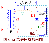
Figure 5-14 is a double voltage rectification circuit. The circuit consists of a transformer B, two rectifier diodes D1 , D2 and two capacitors C1, C2. Its working principle is as follows:  When e2 is positive half cycle (upper positive and negative), diode D1 is turned on, D2 is turned off, current is charged to C1 through D1 , and the voltage on capacitor C1 is charged to the peak close to e2 .
 ![]() And remains basically unchanged. When e2 is negative half cycle (upper negative and positive), diode D2 is turned on and D1 is turned off. At this time, the voltage on Cl is Uc1=
And remains basically unchanged. When e2 is negative half cycle (upper negative and positive), diode D2 is turned on and D1 is turned off. At this time, the voltage on Cl is Uc1= ![]() Adding in series with the power supply voltage e2 , the current charges the capacitor C2 via D2 , and the charging voltage Uc2= e2 peak +1.2E2≈
Adding in series with the power supply voltage e2 , the current charges the capacitor C2 via D2 , and the charging voltage Uc2= e2 peak +1.2E2≈ ![]() . Repeatedly charged, the voltage on C2 is basically
. Repeatedly charged, the voltage on C2 is basically ![]() It is. Its value is twice the voltage of the transformer's power stage, so it is called a double voltage rectifier circuit.
It is. Its value is twice the voltage of the transformer's power stage, so it is called a double voltage rectifier circuit.
In the actual circuit, the voltage on the load is Usc = 2X1.2E2. The highest reverse voltage that the rectifier diodes D1 and D2 are subjected to ![]() . DC voltage Uc1 on the capacitor
. DC voltage Uc1 on the capacitor ![]() , Uc2=
, Uc2= ![]() . Circuits and selection components can be designed accordingly.
. Circuits and selection components can be designed accordingly.
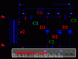
On the basis of the double voltage rectification circuit, a rectifier diode D3 and a filter capacitor C3 are added to form a triple voltage rectifier circuit, as shown in Figure 5-15. 
The working principle of the triple voltage rectifier circuit is: the voltage on the e2 C1 is charged and connected. ![]() , the voltage on C2 is charged close to
, the voltage on C2 is charged close to ![]() . When the third half cycle, D1 , D3 turn on, D2 cuts off, the current is charged by C1 except D1 , and C3 is charged by D3. The charging voltage Uc3= e2 Uc2-Uc1≈ on C3≈
. When the third half cycle, D1 , D3 turn on, D2 cuts off, the current is charged by C1 except D1 , and C3 is charged by D3. The charging voltage Uc3= e2 Uc2-Uc1≈ on C3≈ ![]() Thus, on RFZ,, the DC voltage Usc=Uc1i+Uc3≈ can be output.
Thus, on RFZ,, the DC voltage Usc=Uc1i+Uc3≈ can be output. ![]() +
+ ![]() =3√2 E. , to achieve triple voltage rectification. The first half and the second half of the peak + are the same as the double voltage rectifier circuit, ie
=3√2 E. , to achieve triple voltage rectification. The first half and the second half of the peak + are the same as the double voltage rectifier circuit, ie
In the actual circuit, the voltage on the load Ufz ≈ 3x1.2E2 rectifier diode D3 is also the highest reverse voltage ![]() The DC voltage on the capacitor is
The DC voltage on the capacitor is ![]() . 5-16.
. 5-16.
In this way, by adding a plurality of diodes and the same number of capacitors, it is possible to form a multiple voltage rectification circuit. When n is an odd number, the output voltage is taken out from the upper end: when n is an even number, the output voltage is taken out from the lower end.
It must be stated that the voltage doubler rectifier circuit can only work when the load is light (ie, Rfz is large and the output current is small), otherwise the output voltage will decrease. The higher the voltage doubler, the more obvious the increase in output voltage due to the increase in load current.
The diode used for the voltage doubler rectifier circuit should have a maximum reverse voltage greater than ![]() . A high-voltage silicon rectifier stack is available, and its series model is 2DL. For example, 2DL2/0.2 means that the highest reverse voltage is 2 kV, and the average rectified current is 200 mA. The capacitor used in the voltage doubler rectifier circuit has a relatively small capacity and does not require an electrolytic capacitor. The withstand voltage of the capacitor is greater than 1.5x
. A high-voltage silicon rectifier stack is available, and its series model is 2DL. For example, 2DL2/0.2 means that the highest reverse voltage is 2 kV, and the average rectified current is 200 mA. The capacitor used in the voltage doubler rectifier circuit has a relatively small capacity and does not require an electrolytic capacitor. The withstand voltage of the capacitor is greater than 1.5x ![]() It is safe and reliable in use.
It is safe and reliable in use.
2 in 1 Selfie Stick with detachable blue tooth shutter remote, allows you to take self-snapshot easily or you could separate the blue tooth controller to take group photos and record videos. The only goal of the stick is to help you capture the fun of the moment by blue tooth shutter remote easily.
The maximum length taking snapshot is your arm length plus 27 inch monopod selfie stick ! Imagine that you have two arms length to take self-snapshot and get Face-lift function photos.The folded minimum size 7.87 inch design seems to be more foldable & portable for your pocket or bag perfectly.
Want get satisfying Mufti-angle self-snapshot ?This blue tooth selfie stick tripod stand will achieve your dreams because there are 3 ways to rotate the blue tooth selfie stick tripod by the 225°rotation head with a adjustable knob + 3 modes rotatable phone holder--free combination to get the prefect angle; You can rotate the phone holder and select the phone camera`s using angle (horizontal or vertical or 45°).
Bluetooth Selfie Stick Tripod has High-intensity Aluminum alloy extendable stick and ABS +PC tripod stand with non-slip soft Silicone foot pad that helps the tripod legs won`t slide, so the tripod will be more stable to record video or face time with your family or friends by the remote. Easy to use : Just turn it on, pair it with smart phone via Bluetooth which name is Caiyoule and then take photos or record videos.
Selfie Stick
Selfie Stick,Portable Selfie Stick,Universal Selfie Stick,Bluetooth Selfie Stick
GuangZhou CAIUL Digital Products CO,.LTD. , https://www.caiul-instax.com