introduction
At present, the full autonomous control mode of portable mobile robots is still not mature, and its monitoring system is generally designed by human-in-the-loop semi-autonomous control. In order to meet the structural characteristics of carrying, system miniaturization and embedded type, a portable mobile robot handheld monitoring system was designed and used in the portable mobile robot experimental platform of track structure.
feature design
The handheld monitoring system plays a global role in monitoring and controlling portable mobile robots. The handheld monitoring system can be divided into six major functional modules: video image monitoring module, status information monitoring module, remote control command module, wireless communication module, digital and graph interaction module, and global path planning module (see Figure 1).
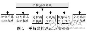
The video image monitoring module performs video monitoring on the environment in which the portable mobile robot is located; the state information monitoring module monitors the state information of the robot itself; the remote control command module implements basic motion command encoding and transmission; the wireless communication module implements motion instruction, state information, Wireless transmission of data such as video signals; digital mapping interactive module realizes digital display of environmental geographic information and human-computer interaction function; global path planning module implements point-to-point optimal path search function.
Hardware system
The hardware system of the handheld monitoring system can be divided into several modules, and each module realizes its relatively independent function.
Hardware structure and interface
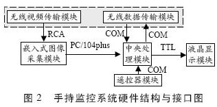
The hardware system of the handheld monitoring system adopts the PC/104plus bus structure based on the PCI bus of the embedded system, and is divided into five modules: wireless communication, embedded image acquisition, central processing, remote controller, and liquid crystal display. The wireless communication module is further divided into a wireless data transmission and a wireless video transmission module. The wireless data transmission module realizes wireless transmission of narrowband data such as motion instructions and status information; the wireless video transmission module realizes wireless transmission of broadband data such as video image signals.
Each module of the hardware system realizes information exchange and data sharing through an interface. The central processing module interfaces with the embedded image acquisition module through the PC/104plus bus to realize the transmission of video image data between the modules. The central processing module is connected to the wireless data transmission module and the remote controller module through a serial port. The central processing module is connected to the liquid crystal display module through a TTL interface. The embedded image acquisition module and the wireless video transmission module realize the transmission of composite video signals through the RCA interface (see Figure 2).
Hardware module implementation
The wireless data transmission module is implemented by a micro power wireless data transmission unit. The embedded image acquisition module is implemented by an embedded image acquisition card of PC/104plus bus structure. The central processing module is implemented by a single board machine with a PC/104plus bus structure. The remote controller module realizes the function of button scanning, command encoding and serial port transmission by designing the circuit board by itself. The liquid crystal display module is realized by a small color liquid crystal screen. The above hardware modules are implemented to meet the miniaturized and portable hardware requirements of handheld devices.
Software system
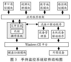
The software system of the handheld monitoring system uses Windows CE (WinCE) as the embedded operating system platform. The monitoring system software includes: operating system customization, device driver development, and application programs. The application is divided into five modules: keyboard scanning module, serial communication module, video processing module, digital mapping module and path planning module (see Figure 3).
CCTV Microphone,Microphone For Security Camera,Cctv Audio Microphone,CCTV Audio Picker
Chinasky Electronics Co., Ltd. , https://www.chinacctvproducts.com