At present, lighting is an important aspect of China's energy consumption. The annual electricity consumption for lighting is about 300 billion kWh, accounting for about 12% of the total power generation. With the economic development, China's lighting power consumption will increase by a large proportion; With the increasingly serious energy crisis and environmental protection issues, China's lighting industry must also take the green energy-saving development path. LED is a kind of semiconductor light-emitting device that converts electrical energy into light energy. It belongs to solid-state light source. As a new type of green lighting, its application prospects are attracting attention. Especially the development of high-brightness white LEDs makes LEDs in the field of lighting. The promotion and application will inevitably lead to a new revolution in the field of lighting.
Compared with current lighting devices such as incandescent lamps and fluorescent lamps, white LEDs have low heat generation, low power consumption (1/8 of incandescent lamps, 1/2 of fluorescent lamps), and long life (tens of thousands of hours or more, 10 times that of fluorescent lamps) ), small size, no pollution, fast response, safe and reliable, etc., is a potential product that is favored by the industry to replace traditional lighting equipment in the future.
At the same time, considering that some lighting products lack brightness adjustment, infrared remote control and other functions, they cannot meet the actual needs of modern lighting. Therefore, this paper designs an infrared remote control high-power white LED lighting system based on AT89S51 single-chip microcomputer. It adopts PT4115 high-power LED constant current driving scheme and infrared remote control technology, through a button encoding based on TC9012 infrared remote controller. Identification and decoding processing, multi-level PWM dimming function for LED light source can be realized by infrared remote control. This design provides great convenience for practical lighting applications while achieving high efficiency and energy saving.
1. System structure and function The lighting system adopts AT89S51 single-chip microcomputer as the main control chip, and selects 3 3W high-power white LEDs as the light source, adopts PT4115 chip to realize LED constant current drive system, and infrared remote control system is controlled by TC9012 remote control transmitter and HS0038 infrared. The receiver is constructed. The system block diagram is shown in Figure 1.
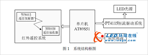
This system uses a home remote control using TC9012 chip as the infrared emission unit. It is widely used, low in price, and has many transmission codes. It can control the multi-level adjustment of the brightness of the LED light source. The infrared receiver is composed of HS0038, which is The integrated component with integrated infrared receiving head, amplification, demodulation and shaping circuit can output the TTL signal recognized by the single chip microcomputer; the infrared remote control information processing is realized by the single chip AT89S51, which mainly completes the identification of the infrared code sent by the remote controller. Decoding, and then generating a PWM dimming signal corresponding to the remote control key value according to the decoding result, thereby controlling the PT4115 constant current driving system to realize LED multi-level dimming function.
2, system principle
2.1 PWM dimming principle From the LED volt-ampere characteristics and mathematical model, it can be seen that the small change of the forward voltage of the LED after the forward conduction will cause large fluctuation of the LED current, and the ambient temperature, LED aging and other factors will also affect the LED. Electrical characteristics, if the LED current is out of control, long-term operation of the LED at high current will seriously affect its reliability and service life. The light output of the LED is directly related to the LED current, so the LED drive circuit should adopt the constant current drive mode when the input voltage and the ambient temperature change.
In practical applications, LEDs generally use two methods to adjust the brightness, namely analog dimming or PWM dimming. The analog dimming and PWM dimming comparison is shown in Figure 2. Analog dimming is to adjust the light efficiency by changing the current flowing through the LED. In addition to the change in brightness, it also affects the light quality of the LED. That is, the current change will inevitably lead to the chromaticity deviation of the LED.

The basic principle of PWM is to keep the LED forward current constant, and by adjusting the ratio of the time the current is turned on and off, the brightness adjustment from 0 to 100% can be achieved. The advantage of PWM dimming is that the current of the LED forward conduction is always constant, and the chromaticity of the LED does not change like analog dimming; while precisely controlling the brightness of the LED, it also ensures the chromaticity of the LED illumination.
  
In order to prevent the human eye from seeing the LED turning on and off, and feeling the light flickering, the PWM dimming frequency is higher than 100Hz. Due to the visual residual effect of the human eye, the eyes will be turned on and off. The brightness is averaged and only the effective brightness determined by the PWM duty cycle is seen. Pay attention to the PWM dimming frequency setting when designing the software.
2.2 Infrared remote control principle Infrared remote control is currently the most widely used remote control method. The infrared remote control device has the characteristics of small size, low power consumption, strong function and low cost, and infrared remote control is widely used in modern electronic products (home appliances, toys, communication devices).
If the key code of the infrared remote controller can be identified and decoded, and used as an input processing signal of the single chip microcomputer system, the conventional matrix keyboard circuit board is too large, the wiring is complicated, and the I/O port is occupied too much; and the remote control is used. The device can realize the long-distance operation control of the human device, and the use is more convenient and efficient.
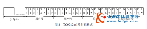
This design uses a TV remote control based on the TC9012 chip as the infrared emission unit. The TC9012 uses a pulse width modulation coding format to encode binary information with different pulse widths. The transmit coding format consists of a pilot code, a user code, a data code, a data inverse code, and an end code. The boot code consists of a high level of 4.5ms and a low level waveform of 4.5ms as the start bit of one frame of data; one frame of data contains a 32-bit code containing two 8-bit user codes, 8-bit data code And the inverse code of the 8-bit data code, the user code is used to distinguish different types of infrared remote control devices, the data code represents the actual pressed key value information, the data inverse code is the negation of each data code, by comparing the data code and data Inverse, it can be judged whether the received key value data is correct; finally, the end bit (SY) is sent as the end of one frame of data. The format of the transmitted code is shown in Figure 3.
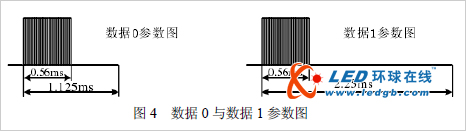
The infrared binary coded information '0' and '1' are respectively realized by a combination of high and low pulses of the order of milliseconds. The combination of pulse width 0.56 ms, interval 0.565 ms, and period 1.125 ms indicates binary "0", and the combination of pulse width 0.56 ms, interval 1.69 ms, and period 2.25 ms indicates "1". The pulse signals are modulated at the duty ratio. It is sent to the 1/3 frequency carrier with a frequency of 38 kHz. The binary parameters "0" and "1" are shown in Figure 4.
The demodulation of the infrared binary signal is done by the integrated infrared receiver HS0038. For the receiving end, when there is no infrared pulse signal, the data output OUT of HS0038 outputs a high level. When there is a high pulse infrared signal, the OUT output is low, so the output signal level is exactly opposite to the transmitting end. This should be noted in the design of the software.
3, system hardware circuit design
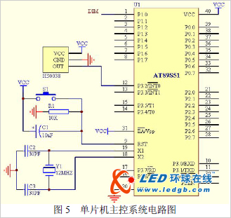
3.1 MCU main control system The design main control system is realized by ATMEL's high-performance single-chip AT89S51. Use a home TV remote control based on TC9012 chip as the infrared emitter of the system; the P3.2 port of the MCU is connected to the data output OUT end of the integrated infrared receiver HS0038; the P1.0 port of the MCU is used as the output of the PWM signal and connected to the PT4115. Chip DIM terminal for PWM dimming control. The single-chip microcomputer recognizes and decodes the infrared code of the infrared remote control 0~9 button and the switch button, and generates the PWM signal corresponding to the key value according to the decoding result, thereby driving the LED to realize different brightness adjustment. The system crystal oscillator circuit consists of a 12MHZ crystal oscillator and two 30PF capacitors; the reset circuit consists of an S1 button, a 10K resistor and a 10uF electrolytic capacitor. The main control system circuit is shown in Figure 5.
Â
3.2 PT4115-based constant current drive system This design LED light source uses a high power constant current drive system based on PT4115. PT4115 is a continuous inductor current conduction mode buck constant current source chip with the following features: 16V~30V wide voltage range input; 2 output current up to 1.2A; 3 multiplexed DIM pin for LED switch, analog Dimming, PWM dimming; 4 output current accuracy up to 5%; 5 conversion efficiency up to 97%; 6LED open circuit protection; 7 output adjustable constant current control method; 8 internal jitter-carrying characteristics, greatly improving EMI. The chip is suitable for driving circuits of various types of green lighting LED lamps, the application circuit is simple, the external components are required to be small and the price is low.
The PT4115 allows easy analog or PWM dimming via the DIM terminal on the chip. This design uses PWM dimming mode to adjust the output current by adding a variable duty cycle square wave pulse signal to the DIM pin to achieve dimming. The LED current is turned off when the square wave voltage amplitude is below 0.3 V, and the LED current is fully turned on when it is above 2.5 V (and below 5 V).
The current output value IOUT is calculated according to this condition:
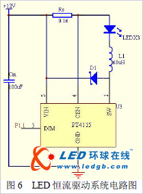
IOUT = (0.1 × D) / Rs (D is the square wave signal duty cycle, Rs is the current limiting resistor) This design LED light source is connected in series, consisting of 3 3W high power white LEDs; each LED rated current About 700mA, forward voltage drop 3.3V~3.6V, brightness up to 150lm. Under the premise of minimizing the power consumption of peripheral devices, the design of constant current drive system using PT4115 is as follows: 1 Determine the input voltage Vin value, when Vin When the difference between the load voltage and the load voltage is about 1.5V, the working efficiency is high. Since the load voltage of the three LEDs is about 10V, the power adapter of the 12V/2A is used for power supply. 2Rs acts as a current limiting resistor and its value determines the maximum drive current of the LED. Considering the junction temperature and heat dissipation requirements of high-power LEDs, the operating current is not too large. The driving system of this paper is designed according to LED working current IOUT=625mA, ie Rs=0.1/IOUT, and Rs selects 0.16 Ω high-precision resistor. 3Cin has a freewheeling and filtering function, using 50V/100uF capacitors. 4L1 is the ballast inductor, the inductor value is 68μH, and the saturation current is 2A.5D1 is a freewheeling diode. When the internal MOS transistor is off, the discharge circuit is provided for the current stored in the inductor L1; State, D1 selects Schottky diode SS24 with small forward voltage drop and fast recovery to effectively reduce system power consumption. The LED constant current drive circuit is shown in Figure 6.
4, system software design
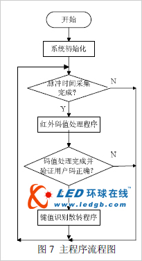
4.1 System main program system The main program mainly includes initialization program (including timer and external interrupt setting), infrared code value processing program and key value recognition and transfer program. The main program flow is shown in Figure 7.
4.2 Infrared Decoding Interrupt Program The infrared decoding interrupt program is used to complete the timing and storage of each high and low pulse time of one frame pulse sent by the remote controller, so as to realize the infrared encoding by analyzing the time of each pulse in the infrared code value processing program. Binary decoding.
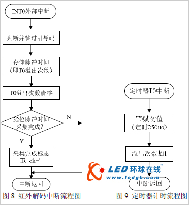
When the remote control has no key press, the infrared receiver HS0038 does not receive the infrared signal, and its OUT terminal outputs a high level; when the remote control has a key press, the high level in the '0' and '1' codes After the infrared receiver HS0038 is inverted, it outputs a low level. Since the OUT terminal of HS0038 is connected to the external interrupt INT0 pin of the microcontroller, the microcontroller interrupt will be triggered (ie, set to a negative edge to trigger the interrupt). Once the system detects a high level signal in the infrared pulse, it triggers the INT0 interrupt, the timer T0 starts timing (timing time is 250us), and the timer T0 overflow interrupt records the number of timer overflows during each pulse; to the next When the high-level pulse arrives, that is, when the interrupt is generated again, the timer overflow number is first taken out, and then the overflow count is cleared and then re-recorded. The time interval between each interrupt and the last interrupt is judged by the number of timer overflows (the time interval is the product of the timer overflow number and 250us), and it can be judged that the received pilot code, code '0' or '1 '. In the interrupt program, first judge and skip the 9ms boot code, and then collect and store the 32-bit pulse encoding time. The infrared decoding interrupt process is shown in Figure 8. The timer timing process is shown in Figure 9.
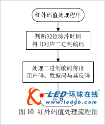
4.3 Infrared code value processing program Infrared code value processing program mainly completes the decoding process of infrared code. By analyzing and processing the 32-bit pulse code time in one frame of infrared code, it judges the binary code corresponding to '0' or '1'. Thus, the inverse of the two 8-bit user code, the 8-bit data code, and the 8-bit data code are determined.
Â
From the TC9012 infrared coding analysis, the "0" code pulse time is 1.125ms, and the "1" code pulse time is 2.25ms. In the actual program processing, the error due to the crystal oscillator parameters of the remote control should be considered, so the timer T0 The overflow number value is taken as 7 (ie 1.75 ms) as the criterion for the '0' or '1' encoding. When the number of overflows is less than 7, it is judged as '0' code. When the number of overflows is greater than 7, it is judged as '1' code, and the 32-bit binary code is processed by 4 bytes to obtain user code, data code and The data is reversed, wherein the data code represents the infrared remote control key value information actually pressed. The single-chip computer can display the decoded key value data code through the digital tube, and obtain the corresponding relationship between the key value of the remote controller and the data code, so as to be used for the judgment processing of the key value recognition and the transfer program, the specific key value decoding result, this paper No longer. The infrared code value processing flow is shown in Figure 10.
4.4 Key-value recognition scatter program Key-value recognition The scatter program is used to identify and correctly transmit the correctly received infrared emitter key-value code. Under the premise of judging the correct user code, the corresponding key data code control is generated to generate the corresponding The PWM signal is used to achieve LED brightness adjustment. This program uses the 0~9 buttons of the infrared remote control as the selection button for the 1~10 brightness of the LED, and uses the remote control switch key as the LED close button. The key-value recognition and dispersion process is shown in Figure 11.

The PWM pulse signal is generated by the MCU using the timer T1 interrupt control P1.0 port output. The high and low levels of the output are input to the DIM terminal of the PT4115 chip to control the on/off state of the LED current, thereby realizing the brightness adjustment of the LED. The timer T1 overflow interrupt is set to 1/2500 seconds (ie, 400 μS), and every 10 pulses are used as one cycle, that is, the frequency is 250 Hz.
In this way, in every square cycle of 1/250 second, the 10-level brightness adjustment of the LED lamp is realized by changing the output duty ratio of the square wave, that is, the brightness level of the LED is determined by the number of high-level pulses in each cycle. The number of high-level pulses is determined by the value of the infrared remote control key, that is, the 0~9 button corresponds to the value of 1~10 brightness level. The timer T1 generates the PWM flow as shown in Figure 12.
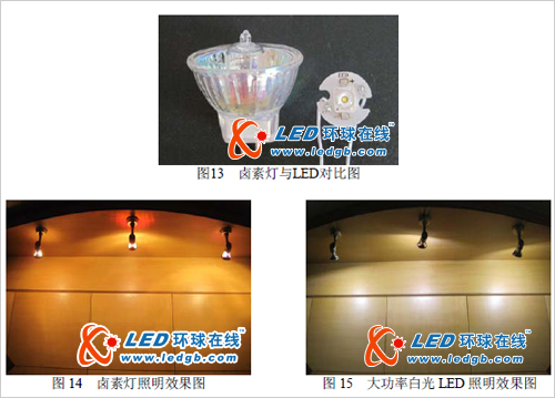
5. Experimental results The design of the home interior wall lamp was replaced by the design of this paper. The original wall lamp adopts 3 220V/20W halogen lamps with a total power of about 60W. The current wall lamp is realized by the high-power white LED lighting scheme of this paper. The lowest power (ie the minimum brightness state of the LED) is about 0.83W, and the maximum power (ie, the highest brightness of the LED) The state) is about 6.52W, which saves more than 90% of the energy compared to the original halogen lighting system. The actual comparison of halogen lamps with high-power LEDs is shown in Figure 13. The experiment proves that the system is stable in operation, precise in dimming, high in energy efficiency, and the infrared remote control function is convenient and fast, and the user can flexibly select different levels of illumination brightness according to requirements. The comparison of lighting effects before and after the transformation is shown in Figure 14 and Figure 15.
6. Conclusion The high-power white LED lighting system based on infrared remote control designed in this paper adopts AT89S51 single-chip microcomputer as the control core, and realizes multi-level dimming control of LED by constant current driving scheme, PWM dimming technology and infrared remote control technology.
The lighting system has the advantages of simple control circuit, precise brightness adjustment, high efficiency, energy saving, practical convenience, and the like, and meets the application requirements of modern lighting. As a new type of green light source, LED is bound to be the development trend of future lighting technology. In the 21st century, it will enter the era of new lighting sources represented by LED.
Â
UFO Round Highbay Light,300W UFO High Bay Light,300W High Bay Light,High LED Brightness Industrial Light
Vietnam JJ Lighting Company , https://www.vnjjlighting.com