In today's increasingly sought-after era, car drivers are increasingly demanding car audio. The trend leader of the world's cars, BMW and Mercedes-Benz, recently put forward new requirements for OEMs in the automotive entertainment system, that is, the car's audio output still works normally when the car starts/stops.
This article refers to the address: http://
Effect on audio output when the car starts/stops
Usually, in order to reduce the carbon dioxide emissions, the car will stop when the car encounters traffic red lights or traffic accidents. When the engine is stopped, the high load will be directly added to the car's battery. At this time, the battery voltage has a rapid decline. When the car engine starts, the car will define its own work according to its own state (such as battery undervoltage, motor temperature, air conditioning, stepping clutch, gearshift, etc.). At these two times, the car's entertainment system is powered by the car battery. Figure 1 shows the performance of the car battery in the above behavior. The 0-t1 time is defined as the normal working condition of the car. The engine is operating normally and the battery is charged. The voltage is maintained at 14.4V. At this time, the car audio amplifier is operating at 14.4V. At time t1, the engine stops and the battery begins to have a rapid discharge process. The final battery voltage drops to approximately U2. At the time t2, the engine starts to start. At this time, the battery has a short circuit of several milliseconds. In this process, the battery voltage will drop rapidly to about 6V. Usually 6V is the worst case. The time after time t3 is the change of the battery after the engine is started up and running.

Usually the previous car audio power amplifier will enter the mute state when the car is stopped and started. That is, there is no sound output. The root cause is when the car engine is in a stopped and activated state. The capacitance of the peripheral circuit to establish a static operating point has a fast discharge behavior, and the rapid discharge causes the circuit to no longer function properly. At present, automotive audio amplifiers on the market will enter the mute state when the battery is rapidly discharged and low voltage, which is determined by the circuit structure of the amplifier.
Solution
Peripheral circuit solution
Figure 2 shows the solution used by typical OEMs to solve the problem of engine stop-start.
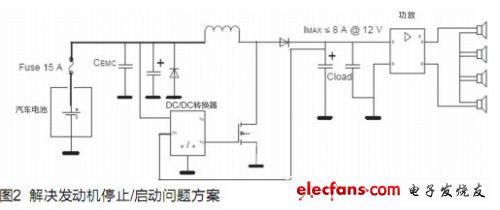
This circuit is a regulated source using DC-DC and some peripheral devices. The maximum peak current supply for the audio power amplifier can be up to 25A. This configuration can solve the defect that the battery's change in the start/stop process causes the audio power amplifier to stop working. However, the disadvantage is that the increase in peripheral devices directly leads to an increase in cost and complexity of the system. STMicroelectronics is the industry leader in automotive in-vehicle entertainment, and the TDA7850LV provides solutions for automotive audio amplifiers for OEMs around the world. Before describing the new solution, let's take a look at the system biasing method of a traditional automotive power amplifier. Chip internal circuit structure solution
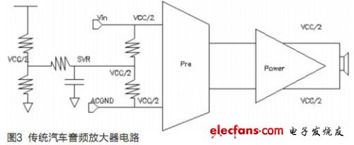
Figure 3 shows the simple structure of a conventional car audio amplifier circuit. As can be seen from the figure, both the input and the output of the amplifier are biased by VCC/2 during operation. This structure must have a fast discharge process at the SVR of the circuit during the rapid power-down of the battery. In the process of rapid discharge, the circuit is unable to perform audio output normally. So the circuit enters the MUTE state. For example, if the battery is short-lived from 12V to 6V, if it does not discharge quickly, the SVR will maintain VCC/2, which is 6V, for a certain period of time. At this time, the preamplifier Pre is also kept at 6V. Obviously the circuit is not working properly. Usually in the design of the audio amplifier, 7V is generally the minimum operating voltage of the chip. So when the power supply drops to 6V, the chip has actually turned off automatically.
TDA7850LV new solution
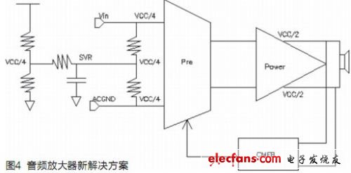
The TDA7850LV is an IC developed based on customer requirements. Its minimum operating voltage is 6V, and it still works during the start/stop of the car. Its structure is shown in Figure 4. The circuit input is biased at VCC/4. The output is biased at VCC/2. For example, if the battery is short-circuited from 12V to 6V and the SVR point is no longer discharged quickly, the SVR will maintain VCC/4 for a certain period of time, that is, 3V. At this time, the input terminals of the amplifier are also kept at 3V. In the figure, the power supply of the preamplifier at this time becomes 6V, the output becomes 3V, and the circuit can still work normally. In this configuration the common mode feedback amplifier must be introduced into the structure to absorb the quiescent current generated during static biasing.
Design result
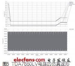
Figure 5 shows the simulated waveform of the TDA7850LV circuit. The power supply voltage drops from 16V to 6V in 2ms. The output OUT1DIFF is displayed as normal. The results prove that the design meets the requirements of the customer.
MLF advise many types of USB chargers , USB Power Adapters, USB network adpaters . 2.0 Usb Adapters as well as 3.0 USB ac adapters .and also 3.1 USB type. USB power adpater widly use in various industry.Let us match a high quality Usb Power Adapter for your device !
The main type is single USB Adapter , but also dual USB and mutiple USB port type also .can charge the two or more devices at one time. Please don't hesitate to contact if you want to know more details about the USB adapters!
USB Adapter
Usb Power Adapter,Usb 2.0 Adapter,Usb Power Supply,Usb Network Adapter
Meile Group Limited , http://www.hkmeile.com