Abstract: This article will mainly explain the application of array microphones in TV, which can greatly enhance the user experience; and put forward some technical solutions to solve echo.
This article refers to the address: http://
Keywords: chat TV; array microphone; echo; experience; calibration
Foreword
With the promotion and implementation of the national three-network integration policy, TV sets as home entertainment terminals will also bring some very positive changes. For example, Shenzhen Skyworth took the lead in research and development of "chat TV" in February 2010, followed by Hisense, TCL and other home appliance manufacturers also launched similar products.
In chat TV, the voice collection of the microphone becomes very important. At present, most chat TVs basically use a single microphone for radio reception, which may be a wired microphone or a wireless microphone. Receiving a single microphone will cause the following problems.
â— User experience is not good.
That is to say, in the process of video chat, the user needs to hold the hand or talk as close as possible to the microphone, which is not good; especially when many family members want to chat together, it is even more crowded.
With a wired microphone, the cable is awkward and affects the decoration of the home; wireless microphones are prone to breaks when people move faster; and no matter which method is used, it takes a while to replace the battery or Charge again.
â— Higher cost.
At present, on the chat TV, the wireless microphone and the carrier modulation are 2.4 GHz, which has become the mainstream, but the cost of this method is obviously high.
In response to the above two problems, we propose to use the array microphone to be applied to the TV, which can better solve these two problems.

Array microphone
Array Microphone, also known as Microphone Array, sets up two or more microphones, and uses these microphones to detect audio. The obtained data is compared with a digital signal processor (DSP). To restore the original appearance of the sound and eliminate background noise. Array microphones are currently one of HD Audio's standards. Array microphones are already supported in Windows Vista.
The array microphone analyzes and processes the picked multi-channel speech signals, so that the main beam of the beam pattern formed by the array is aligned with the target speech, and the “zero point†points to the interference source to suppress the interference signal, so as to obtain the target speech as much as possible. The beam direction and the main lobe width of the beam are closely related to the pitch of the microphone, the number of microphones, the position of the microphone, the incident angle of the sound source, and the sampling frequency. The formation of the beam not only eliminates the need to manually adjust the microphone directivity when using a single microphone, but also greatly improves the signal-to-noise ratio of the output speech, so that high-quality speech can be obtained without manual intervention.
When talking in a traditional microphone, people need to be as close as possible to the microphone. For the system, the “main tone†is spoken close to the microphone, and the system gets a large input. For the noise next to it, or the voice output by the interlocutor from the speaker, the amplitude is relatively small, and both belong to the "interference sound". In this way, the system can more accurately filter out the "interference sound" and retain the "main tone". In this traditional microphone pickup process, the problem of echo is not outstanding. When applying an array microphone, the echo problem needs to be focused.
Echo refers to the sound that is broadcast on the speaker while being heard by the receiver. The voice signal is also picked up by the microphone in various ways and returned to the original speaker. The paths through which the echo passes are different, resulting in different delayed echoes, including direct echo and indirect echo. Direct echo means that the sound broadcast by the speaker enters the microphone directly without any reflection. The delay of this echo is the shortest, it is the same as the speech energy of the far-end speaker, the distance between the speaker and the microphone, the angle, the playback volume of the speaker, The pickup sensitivity of the microphone is directly related. The indirect echo refers to the collection of echoes generated by the sounds emitted by the speakers after passing through different paths (such as houses or any items in the house) after being reflected one or more times into the microphone. Any movement or change in the house will change the echo path. Therefore, the characteristics of this echo are multipath and time varying.
In the array microphone application, since the person no longer needs to be close to the microphone when speaking, the influence of the person's "main tone" on the microphone may be lowered, that is, the "interference sound" next to it may interfere with " The vocal" causes the system to not correctly identify which is the true "sound". Especially during the chat, the voice of the other party comes out of the speaker. If the sound is louder, it will be re-acquired by the microphone, and the other party will hear the words he himself said again or more. This is the biggest problem in applying array microphones.
In short, in the application of array microphones, it is recommended to pay attention to the following questions: whether the radio range is wide enough; whether the radio distance is far enough; whether the radio effect is clear enough; whether the echo problem is better eliminated. The range of the radio can be adjusted by changing the number of microphones and the position of the microphone; and the distance and clarity of the radio can be adjusted by adjusting the sensitivity of the microphone. This article does not discuss too much. Since the problem with echo is the most difficult to deal with, this article also attempts to come up with some personal ideas.

Application of array microphone on TV
At present, the technology development of array microphones has been relatively mature. In the case that the voice reception distance of human voice is not very far, and the space is not large, and the range of radio reception is narrow, array microphones have been widely used, such as laptops, car Bluetooth. Equipment and so on. Similarly, the array microphone can also be applied to the TV, allowing users to chat freely with distant family members, friends, etc. (Figure 1).
When an array microphone is used on a television set, a farther distance is required, and a wider range of radio is required, and these problems can be easily solved, but the problem of echo becomes more prominent. Because the TV is the entertainment center of the home, the speaker volume output of the TV may be relatively large, and most of the microphones are designed on the TV. The sound of the far-end speech comes out of the speaker, which is easily picked up by the microphone and then transmitted. On the other side of the original speaker, in a serious situation, it may also form self-excitation.
In the process of TV chat, if there is an echo, it will cause the speaker to feel uncomfortable; and the voice superimposed, resulting in unclear speech, so try to eliminate the echo. The use of the TV and the environment are different. For example, the volume of the speakers varies greatly, and the layout of the space is also very different. These are factors directly related to the echo, and these factors are uncontrollable and unpredictable. Estimated factor. In order to solve the problem of echo that may be generated by applying an array microphone to a television set, an adaptive filter needs to be designed inside the system. The basic idea of ​​the adaptive filter is to estimate the characteristic parameters of the echo path, generate an analog echo path, and derive the simulated echo signal. Then, the echo signal simulated by the adaptive filter is subtracted from the received signal to implement echo cancellation.
The architecture of the adaptive filter is shown in Figure 2. The input of the filter shown in the figure is x(n)={x(n), x(x-1), ⋯x(n-N+1)}T, and the weight coefficient of the filter is h(n) ={h1(n), h2(n), ⋯hN (n)}T, d(n) is the desired output signal, and d^(n) is the actual output of the filter, also called the estimated value. e(n) is the error, and e(n)=d(n)-d^(n). The filter coefficients are adjusted by the error through an adaptive algorithm such that the filtered actual output is close to the desired output signal.
The block diagram of the application in actual TV is shown in Figure 3. In the figure, f(n) represents the speech signal from a distant place; r1(n) is the echo set generated by f(n) from the speaker, passing through different echo channels, and is received by the array microphone; s(n) is local The speech signal spoken by the user; r(n) is an adaptive filter pre-processing f(n) to estimate the echo generated by the f(n) signal, and its dynamic estimate is r(n). Then, by calculation, the sound signal transmitted by the local user should be u(n)=y(n)-r(n)=s(n)+r1(n)-r(n). In an ideal state, if the echo estimate r(n) produced by the adaptive filter is equal to the actual echo set r1(n), ie r1(n)-r(n)=0, then the echo will be exactly eliminate.
Since the user's usage environment is very different, it is difficult to make the output r(n)=r1(n) by dynamically modifying the weight coefficient of the filter by the algorithm inside the adaptive filter alone. Therefore, if the adaptive filter dynamically corrects the weight coefficient inside the DSP, take into account the environmental factors used in the TV, fully analyze the various conditions of the echo channel, and combine the "inside and outside" factors to dynamically correct the filter weight. The coefficient, which will make r(n) closer to the actual r1(n), thus more effectively canceling the echo. A block diagram of the system with an internal calibration signal is shown in Figure 4.
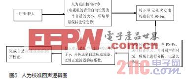
The most important of these is the addition of an internal calibration unit that stores some specific audio test signals Fn. The frequency included in the vocals is mainly from 300 to 3400 Hz, so the internal test signal Fn can be sampled from this frequency interval, such as Fn=300 Hz, 400 Hz, 500 Hz, etc., and so on. The logic of this is shown in Figure 5.
For example: When the user finds that the echo is large during the chat process, the user can manually issue a calibration command by means of a button of the remote controller or a button on the key control board. At this time, the internal calibration unit will issue the relevant test signal Fn one by one. The test signal passes through the main channel and passes through the power amplifier to emit sound from the speaker. The sound is then picked up by the array microphone through different echo channels and sent back to the internal calibration unit. Since the test signal is an inherent signal, the internal calibration unit can accurately compare the difference between the test signal and the echo, taking into account the environmental related echo factors, resulting in a new correction factor γ.
The correction factor γ is sent to the adaptive filter, and the adaptive filter corrects the weight coefficient of the filter. This weight coefficient can be said to some extent to consider the influence of the external environment on the echo, so the adaptive filter produces r(n) will be closer to r1(n), which will better eliminate echo.
summary
It is foreseeable that the chat function will become one of the main functions of the TV in the future, and the application of the array microphone in the TV set can get rid of the dependence on the traditional form microphone, and bring a better experience to the user; The elimination process is a guarantee that the array microphone can be widely used in television sets.
The concept of strong electricity is relative to weak electricity. Strong and weak currents are separated by voltage. The working voltage is more than 24V AC is strong, and the following is weak. Strong wires generally refer to transmission wires with an AC voltage of more than 24V. Such as home lights, sockets, etc., the voltage is 110 ~ 220V. Strong wires can also affect nearby communication lines. The following describes the knowledge of strong wire protection.
(1) Different AC frequencies
The frequency of strong electricity is generally 50Hz (Hz), which is called "power frequency", which means the frequency of industrial electricity: the frequency of weak electricity is often high frequency or ultra-high frequency, measured in KHz (kilohertz) and MHz (megahertz).
(2) Different transmission methods
Strong electricity is transmitted on transmission lines, and weak electricity transmission is divided into wired and wireless. The radio transmits electromagnetic waves.
(3) Different power, voltage, and current
Strong electric power in KW (kilowatts), MW (megawatts), voltage in V (volts), KV (kilovolts), current in A (ampere), kA (kiloampere); weak electric power in W (watts) , mW (milliwatts), voltage in V (volt), mV (mV), current in mA (milliampere), uA (microampere), so its circuit can be printed circuit or integrated circuit composition.
There are also high-frequency (hundreds of KHz) and medium-frequency devices in high-voltage power supplies, but the voltage is high and the current is large. Due to the development of modern technology, weak electricity has penetrated into the field of strong electric power, such as power electronic devices, wireless remote control, etc., but these can only be regarded as the weak electric control part in strong electric power, and it is still different from the controlled strong electric power.
According to the basic principle of weak electricity transmission signals and strong electric conduction, we can easily distinguish between strong electricity and weak electricity. For example, although electric shavers, flashlights, etc., use only two dry batteries (3V), we cannot think that they are weak because the voltage and current of the appliances are small, because they conduct electricity rather than signals, so they should be classified as strong. class.
From the above description, the relationship between the four can be roughly stated as follows:
High voltage must include strong electricity, and high voltage does not necessarily belong to high pressure.
Low voltage must include weak electricity, weak electricity must belong to low pressure;
Low voltage is not necessarily strong, and strong power is not necessarily low pressure.
The use of strong electricity
Strong electricity generally refers to the mains power system\lighting system and other power supply and distribution systems, including air conditioning lines, lighting lines, outlet lines, power lines, high-voltage lines and the like. There are two types of weak electricity: one is the state-designed safe voltage level and control voltage and other low-voltage electric energy, and there are AC and DC points, such as 24V DC control power supply, or standby power supply for emergency lighting. The other is information sources that carry information such as voice, images, and data, such as audio, video lines, network lines, and telephone lines. DC voltages are generally within 36V. Electrical appliances such as telephones, computers, televisions (cable television lines), audio equipment (output lines), broadcasting systems, and building automation (such as access control and security) in household electrical appliances are all weak electrical equipment.
In power systems, voltages below 36V are called safe voltages, voltages below 1kv are called low voltages, voltages above 1kv are called high voltages, and lines that directly supply power to users are called distribution lines, such as user voltages are 380/220v, It is called a low-voltage distribution line, which is the strong electricity in home decoration (because it is the highest voltage for home use). Strong electric generally refers to direct current voltage above 24V. Such as home lights, sockets, etc., voltage 110V ~ 220V. Electrical appliances for home lighting, electric water heaters, heaters, refrigerators, televisions, air conditioners, audio equipment, etc. are all electric equipment.
High Current Cable,Pvc Insulated Copper Core Wire,Bvr Electric Cable,Bv Power Cable
Jiangsu QiSheng Cable Co., Ltd. , https://www.shuaihe-cable.com