Thermal design of DWDM communication equipment
The development of contemporary communication technology is extremely rapid. The speed of communication equipment has grown from 155M in previous years to 622M, 2.5G, 10G, and even 40G today. To be sure, it will develop towards a higher speed in the future. Multi-layer circuit boards and high-density surface-mount components are commonly used in high-speed transmission equipment such as SDH and DWDM, but with it comes heat dissipation that cannot be ignored. When the temperature inside these devices is too high, it may cause errors in the electrical branch or optical branch or signal interruption, which seriously affects the communication quality and the long-term normal use of the device. Therefore, the device must be carried out during the system design process. Careful and meticulous heat dissipation design.
Dense wavelength division multiplexing (DWDM) equipment heat dissipation design 32-wave DWDM equipment includes three categories: optical terminal equipment, optical relay equipment and optical add-drop multiplexing equipment. It adopts a flexible modular structure and is inserted into different sub-frames into different device of. The characteristics of the mechanical mechanism of the 32X2.5G DWDM terminal are introduced below.
The 32X2.5G DWDM terminal is composed of an optical amplification and monitoring subrack and two optical channel subracks. The optical amplification and monitoring sub-rack and the optical channel sub-rack adopt the structure of a backrest chair, and the optical and electrical signals of the sub-rack adopt front outlets, and the height is 11U. The 3U power sub-rack provides -48V power, and the rack adopts a 21 ″ standard rack. The power parameters and environmental conditions of the sub-rack during operation are shown in Table 1 and Table 2.
Table 1 Sub-rack power number
name | Power (W) |
Optical amplification and monitoring subrack | 110 |
Optical channel subrack | 245 |
DWDM terminal equipment | 600 |
Table 2 Working environment conditions of DWDM equipment
Environmental conditions | Temperature (℃) | humidity(%) |
Long-term guaranteed performance | 0 ~ 40 | 10 ~ 90 |
Short-term working scope | -5 ~ 50 | 10 ~ 95 |
Transportation and storage | -25 ~ 70 | <95 |
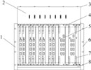
The natural heat dissipation method shows from Table 1 that the power of the DWDM terminal is not large, but there are as many as 18 single disks in each sub-rack. A tight metal box is formed between the two, which affects the normal heat exchange between the single disk in the subrack and the external environment. At the same time, the device needs to run under harsh environmental conditions for a long time. Sensitive chip and single disk. Figure 1 is a 21 "DWDM terminal equipment optical channel sub-frame structure diagram.
 |
|
The thermal design of the sub-rack mainly includes the thermal design of the single plate and the sub-frame. The specific methods are as follows.
(1) Install a small fan or copper, aluminum heat conducting strips and heat dissipation fins on the electronic components with higher power.
(2) The orientation of the installation of electronic components on the PCB board should conform to the flow characteristics of the cooling air flow, that is, the direction of the air flow.
(3) Arrange the components reasonably, put the heat-resistant components at the inlet of the cooling airflow, and the components with good heat resistance at the outlet of the cooling airflow.
(4) The extractor uses materials with high thermal conductivity. Because the outer side of the puller is directly exposed to the ambient air, it actually plays a role of heat dissipation of the heat conducting fins. A large number of pullers can effectively reduce the temperature inside the subrack.
(5) The panel, upper and lower trays, left and right side plates, and front and rear covers are all made of aluminum alloy with high thermal conductivity, and the same circular holes are punched out at the symmetrical positions on the surface of the upper and lower trays to ensure smooth airflow. Considering the need for electromagnetic shielding, the size of the round hole should generally be less than 5 mm.
Forced Ventilation and Heat Dissipation-Thermal Design of the Whole System In DWDM equipment, it is not enough to adopt natural heat dissipation method for the sub-frame. You must also use a fan to perform forced ventilation and heat dissipation. The specific method is to install a fan box-fan subrack under each subrack in the equipment, and install a fan subrack at the top of the rack to reduce the temperature in each subrack through forced ventilation. The structure of the rack is shown in Figure 2.
The key to adopting forced ventilation and heat dissipation design is the design of the fan subrack and the correct selection of air ducts in order to reasonably control and distribute airflow.
According to the overall power of the DWDM terminal, it is determined that the fan subrack is composed of three 3.5W DC fans connected in parallel, and the height of the subrack is 1U. In order to form an air duct, large circular holes are punched on the upper and lower surfaces of the fan subrack, and the axis of the fan is installed in the center of the functional subrack; at the same time, a fan subrack is installed on the top of the rack. The front and rear doors have small round holes, so that the fan can draw ambient air into the rack. The air flows by the sub-rack to take away part of the heat, and finally is discharged through the square hole on the top of the rack to form an air duct. This design ensures the air intake of the rack and the circulation of hot air, which plays a good role in heat dissipation.
In order to ensure the normal operation of the fan subrack and DWDM terminal equipment, an alarm light is provided on the fan subrack panel to detect the fan's working situation in time; the temperature detection function is designed on the power supply and environmental monitoring board on the top of the rack. An alarm is issued when the working temperature of the subrack exceeds the warning temperature.
Test the thermal design of the DWDM terminal equipment. The high-temperature test results of the DWDM terminal equipment are shown in Table 3. The test results show that the thermal design of the product fully complies with the requirements of ITU-T and can be operated stably and reliably for a long time.
Conclusion Thermal design is an issue that must be considered in the design of high-speed communication systems such as DWDM. The quality of the design directly affects the stability and reliability of the equipment. The design method described above is simple and practical, and also has a good reference for the thermal design of other equipment.
About Key Accessories:
As we know ,everyone needs to use keys ,we use them in our household ,in our cars ,in our office,so we have many keys on hand ,in order to keep our keys well ,we may need keychains ,key rings and key covers for collecting keys in line ,and protecting our pockets,we don't want our life to be messy or lost our keys!
What we can do on Key Accessories?
Our factory have some common keychains to sell,and our main business is OEM ,we can help you to do Silicone Keychains/rings,PVC keychain,Silicone Wristband keychains,Silicone Key Cover,if you have your ideal designs ,please tell us ,we can help you to achieve by your requirements!
Some Key Accessories photos for your ref.


Key Accessories
Key Accessories,Custom Made Keychains,Custom Pvc Keychain,Silicone Key Sleeve
OK Silicone Gift Co., Ltd. , https://www.oemsiliconegift.com