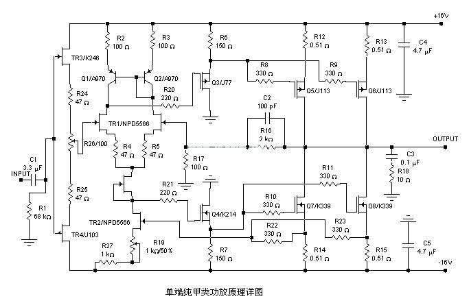
| A 20W single-ended pure Class A power amplifier circuit diagram, the circuit is very simple, and few components are used. It is in line with the principle of "briefness first". The materials are common and easy to imitate. I see that many audiophiles are interested in single-ended pure Class A amplifiers. The schematic diagram is as follows: | ||||
 | ||||
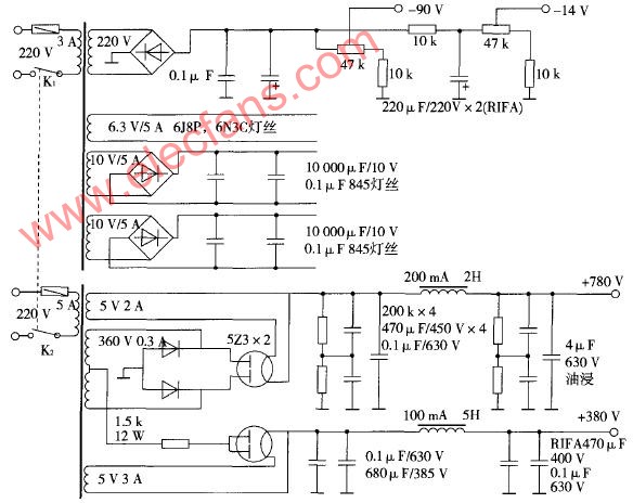
| Circuit principle and design ideas, the whole circuit can be divided into four parts: Input stage: The core circuit is a differential amplifier circuit composed of two BC559s. The 22K resistance to ground is the bias resistance of the triode. Its size also determines the input resistance of the entire power amplifier. The 8.2K resistor is the common emitter resistance of the differential pair tube, which determines the common mode rejection ratio of the differential circuit and the static working current of this stage. The voltage signal generated when the current amplified by the input stage flows through the 1K adjustable resistance is directly transmitted to the next stage. The 1UF capacitor is the input capacitor of the whole machine, and its size and manufacturing materials have a great influence on the sound quality. According to theoretical calculations, the capacitance of 1UF and the input resistance 22K form a high-pass filter circuit, and its low-end corner frequency can be calculated by the following formula: f = 1000 / (2 * 3.14 * 22 * ​​1) = 7.2HZ. (In the past, when the low-end frequency response of the amplifier was positioned at 20HZ, it was still acceptable. Now that digital audio sources are popular today, it seems that it is still higher. It is still acceptable to set the low-end corner frequency below 1HZ.) The importance of this capacitor must be selected from imported audio special coupling capacitors of good quality. Among the domestic capacitors, the brand of Xindak is still trustworthy. After the trial by the author and friends, the effect is satisfactory, but the volume is slightly larger. In addition, when designing the circuit board, we must consider whether it can be installed. The 8.2K resistance determines the static working current of the input stage transistor, which can be estimated by the following formula (two-tube value): VCC / 8.2K = 20 / 8.2 = 2.4MA. Since the static working current of the input stage transistor has a great influence on the sound quality, the size of the resistor can be adjusted to meet its own requirements. (The transistor's static working current is small and the signal-to-noise ratio is high, but the sound quality is dry and the bass is thin. If the current is larger, the sound quality is warm and the bass is thick, but the transistor-specific high-frequency noise and current sound reflected in the audio will also increase Make the signal-to-noise ratio drop. It is more appropriate to use 2.4MA for this machine.) Voltage amplifying stage: In order to simplify the circuit, this machine uses a triode BD139, using common-emitter amplifying circuit, and also uses a bootstrap circuit. The quiescent current at this level can be estimated by the following formula: VCC / (1.5k + 1.5k) = 6.8MA. The small capacitor of 100P is used for frequency compensation, the capacity should be as small as possible, if there is no high frequency self-excitation, you can not use it. (Of course, the existence of this small capacitor has a subtle adjustment effect on the sound quality. How to deal with it depends on your preference.) In order to ensure the amplitude characteristics and linearity at the time of large signal output without adding too many components, this machine uses a bootstrap circuit, which is composed of a 100UF capacitor and two 1.5K resistor voltage divider circuits. In the audio industry, there are many criticisms of the bootstrap circuit, which is considered to be a positive feedback, which has a greater negative impact on the sound quality. Due to the early debut of this circuit, the design premise is "conciseness first", and perhaps the consideration here is not so comprehensive. Output stage: The two MJE2955 and the surrounding components in the upper part of the schematic form a single-ended pure Class A amplifier circuit, and the lower half uses two MJE2955 as the core to form a high-current constant current source circuit. The constant current value is the static current of the output stage. It can be estimated according to the following formula: 0.65 / 0.25 = 2.6A. (Among them, 0.65V is the forward voltage drop of the PN junction of the emitter junction of the silicon transistor.) The static working current of the power amplifier tube of the output stage can be adjusted by changing the value of the 0.25 resistance. In this circuit, a 20W pure Class A output is required on an 8-ohm load. The current of 2.6A seems a bit large. In fact, there is a formula to estimate: P = 2 * I * I * RL, so that there is about 1.1A can meet the design requirements, but the impedance of our speakers is not the same as the pure resistance. Sometimes, at a specific frequency and extreme conditions, the impedance may drop very low. According to the design of the circuit, if a load of 4 Euros is used, the pure Class A output of 40W can also be completely achieved! Only the scientific attitude and rigorous thinking of this design are worth learning. Loudspeaker impedance compensation circuit: Because the loudspeaker we use is an inductive load, in order to make the load of the amplifier close to a pure resistance, there is generally a compensation circuit in series with a resistor and a capacitor at the output of the power amplifier. The resistance value of the resistor and the standard of the speaker It is said that the impedance is equivalent, and the value of the capacitor is 0.1UF-0.22UF, which will not be detailed here. Precautions for installation and commissioning: Power supply part: Due to the poor common-mode suppression capability of the pure Class A single-ended power amplifier and the large quiescent current of the machine, the requirements for the power supply are very high. It is best to use an inductive filter circuit, but for The manufacture of the inductor and the treatment of the electromagnetic interference generated after application are very headaches. The use of a voltage regulator circuit is also a good choice. However, the cost and heat dissipation problems also come, or bear with it. Finally, the capacitor filter circuit was selected. The capacity of the transformer should be above 1000W, the secondary voltage is four groups of 15-18V and the current capacity is above 10A. Two pairs of two voltages are connected in series to provide left and right sounds. Road, the rectifier full bridge must choose the current above 25A, the withstand voltage does not need to be too high, 200V is enough. The capacity of the filter capacitor should not be less than 22,000 UF per channel of the positive and negative power supply. Of course, the larger the better, but it is best to use multiple small-capacity capacitors in parallel to achieve the required capacity. Non-polar capacitors with good high-frequency characteristics of capacitance are even more necessary. Although the cost has increased, the effect is much better. Fortunately, the price of the 25V electrolytic capacitor is lower. Because "in a good power amplifier, the cost of power supply accounts for half!" The author appreciates this view very much. If the dual mono design is adopted, it is better if the transformer-rectifier filter circuit-amplifier circuit-output are all independent. Production, debugging: It is precisely because of the simple circuit, so the sound quality is almost determined by the characteristics of the original device. The transistors marked in the picture now seem to be less feverish, and readers can replace them according to the current trend. Due to the high heat value of the circuit, the reliability of the components must be high. The resistance should always be a 1 / 2W metal film resistor. Because the amount of capacitor used is small, it must be fine. As long as the quality of the original device and welding technology can be guaranteed, the debugging of the whole machine is very simple. Before powering on, the 1K adjustable resistor is placed in the middle position. After powering on, adjust the resistance so that the output terminal is as close to 0V as possible. , The rest are guaranteed by the circuit and the original device. Keep it unloaded for more than half an hour, observe that the temperature of the radiator is not too high, other components are normal, and the potential of the retest output is not too large, and it can be put into use. Since the components of the power amplifier still need to be aged, it may take a long time for you to hear the beautiful sound. There is no protection circuit involved in this article. In order to protect your expensive speaker system, it is strongly recommended to install a safe and reliable speaker protection circuit. | ||||

Follow WeChat

Download Audiophile APP

Follow the audiophile class
related suggestion
The principle of the field effect tube to control the working current is completely different from that of ordinary transistors, which is much simpler than ordinary transistors.

The five-pole power amplifier tube FD422 is used to make a single-ended Class A power amplifier. The design of this circuit is based on the principle of "simpleness first", which can reduce installation errors. Follow first ...

845 single-ended Class A amplifier circuit diagram will be 6N8P
What is a pure Class A amplifier The so-called Class A or pure Class A amplifier is actually two sub-classes of the power amplifier classified by static operating point. According to this division, ...
Field effect tube characteristics and the artistic charm and evaluation of the production of audio amplifiers with single-ended Class A amplifiers Audio amplifiers can be divided into electronic ...
Single-ended Class A power amplifier circuit Below, we introduce a single-ended pure ...
Circuit characteristics 1. This power amplifier uses a current negative feedback circuit (Japan's famous golden voice most power amplifier ...
The power amplifier made with the voltage regulator set is a pioneering idea for electronics enthusiasts ...
![[Photo] NE5532 20W pure class A amplifier driven in parallel](http://i.bosscdn.com/blog/20/06/41/5131158379.jpg)
This is a Class A power amplifier with an output power of 18W. The final stage uses a current series negative feedback circuit (the bypass capacitors at both ends of the output stage self-biasing resistor are cancelled)
Many audiophiles are happy to make power amplifiers, but most of them are limited to some single-chip sets such as LM1875, LM3886, LM4766, TD ...
'+ data.data.username +' '; dom + ='
Heavy Duty Connector, also known as HDC, is widely used in construction machinery, textile machinery, packaging and printing machinery, tobacco machinery, robots, rail transit, heat runner, electric power, automation and other equipment requiring electrical and signal connection. The international advanced features of Heavy Duty Connectors in structural design and material usage make the connectors outstanding in electrical performance.The reliability of the electrical connection system can not be achieved by the traditional connection method.
We developed numerous professional tools for practical use as well as provide effective guarantee for your safe and accurate installation of heavy duty connectors.
Crimp Contact,Contact Crimping Tool,Heavy Duty Connector Tool,Heavy Duty Power Connectors
Suzhou WeBest Electronics Technology Co.Ltd , https://www.webestet.com